
Rotor iron core magnet assembling device

A technology of rotor core and assembly device, applied in the direction of manufacturing stator/rotor body, etc., can solve problems such as injury to operators, difficult to remove magnets, complicated magnet assembly process, etc., and achieve the effect of reducing removal problems.

Pending Publication Date: 2019-06-21
深圳市泉天下智能装备科技有限公司
View PDF0 Cites 0 Cited by
  • Summary
  • Abstract
  • Description
  • Claims
  • Application Information

AI Technical Summary

Problems solved by technology

However, this invention does not solve the problem of removing the magnetic isolation pad during the magnet assembly process. The operator must manually remove the magnet from the magnetic isolation pad. It is not easy to remove the magnet due to the magnetic force, and then put the magnet into the set guide groove.
The magnet assembly process is complicated, and the problem that the operator may be injured due to the adsorption between the magnet and the iron core during the assembly process has not been solved. The main difficulty of the magnet assembly process has not been resolved.

Method used


Image

  • Rotor iron core magnet assembling device
  • Rotor iron core magnet assembling device
  • Rotor iron core magnet assembling device

Examples


Embodiment Construction

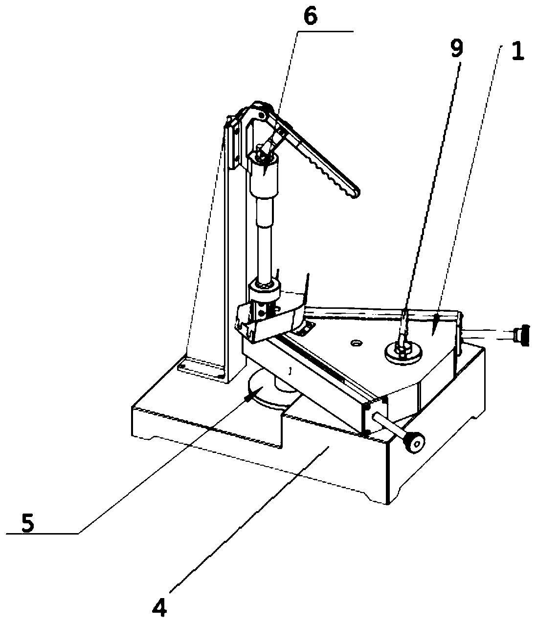
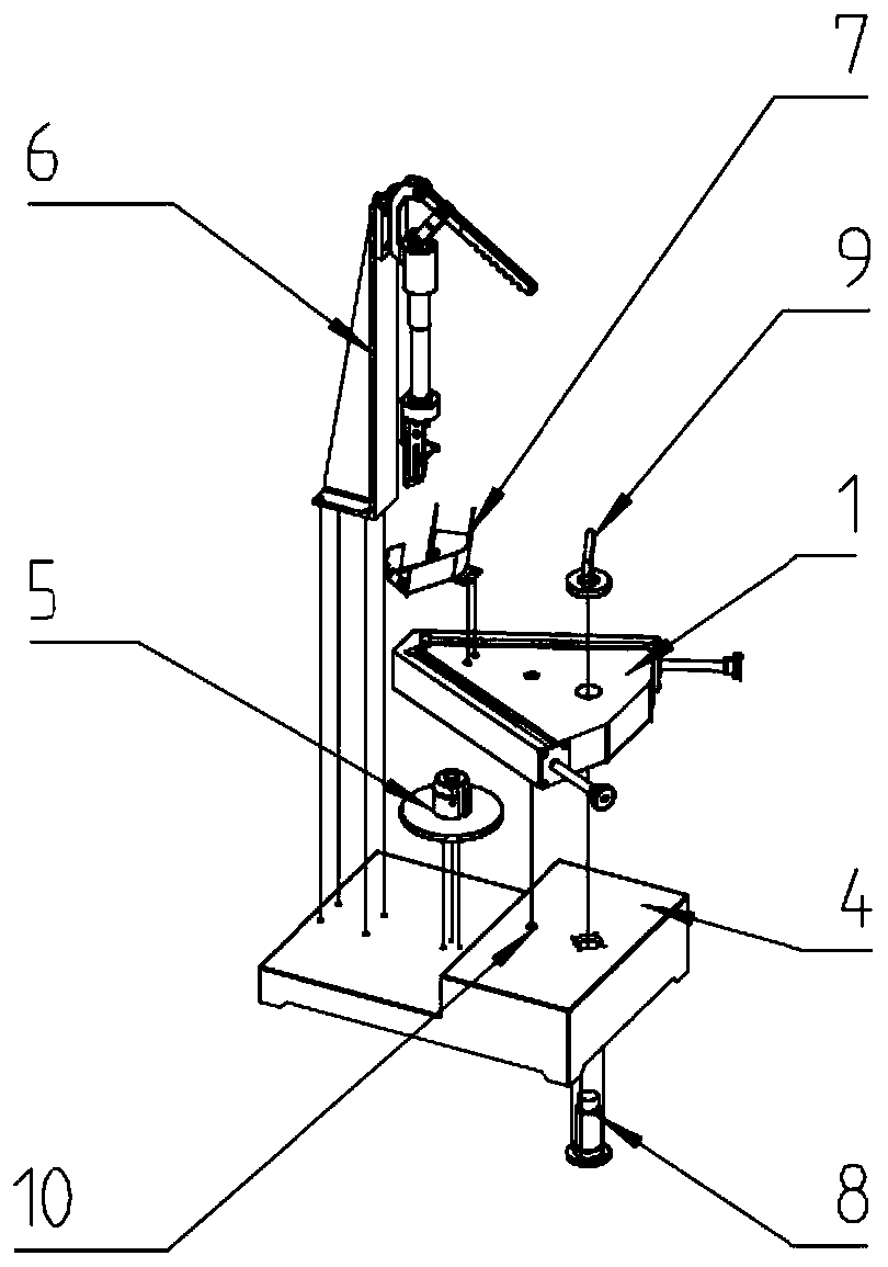
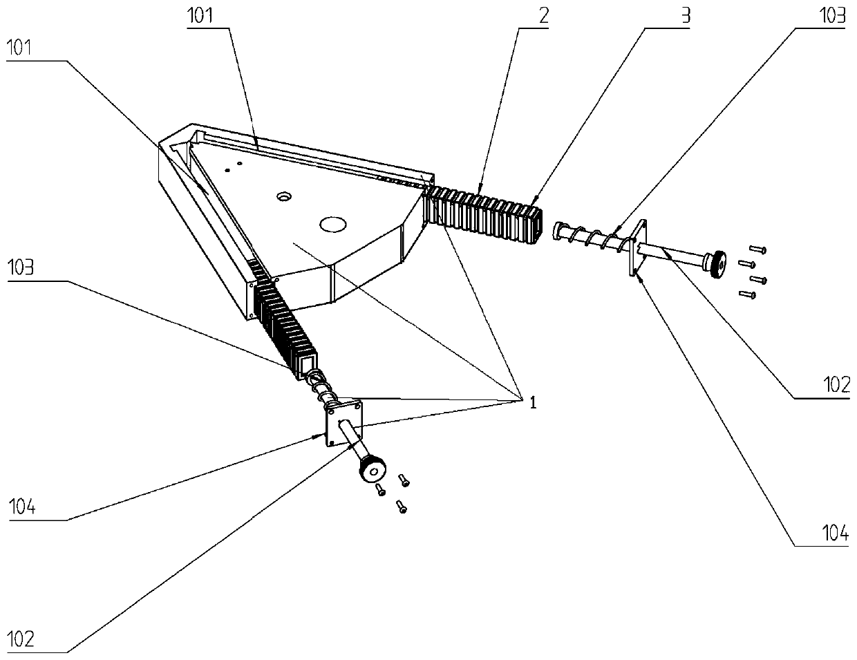
[0029] The present invention will be further described below in conjunction with the accompanying drawings and specific embodiments.

[0030] refer to Figure 1 to Figure 13 , the present invention provides a rotor core magnet assembly device, which includes a stepped base 4, a pressing magnet assembly 6 and an indexing plate assembly 5 that are detachably arranged on the lower steps of the stepped base 4 in turn, Disassemble a magnet bin mechanism 1 that is arranged on a step on the stepped base 4, and a magnetic isolation pad purge tray 7 that is arranged directly above the magnet bin mechanism 1; the magnet bin mechanism 1 includes two horizontal magnet placement channels 101 And two magnet push rod assemblies, two magnet placement passages 101 intersect at the head of the magnet bin mechanism to set a magnet outlet through up and down, each magnet placement passage 101 corresponds to a magnet push rod assembly, for placing a number of rotor core magnets arranged at interva...


PUM


Abstract

The invention discloses a rotor iron core magnet assembling device. The rotor iron core magnet assembling device comprises a stepped base, a pressing magnet assembly and a dividing plate assembly, a magnet bin mechanism detachably arranged on the stepped base, and a magnetic isolation pad blowing-sweeping tray arranged right above the head of the magnet bin mechanism, wherein the pressing magnet assembly and the dividing plate assembly are detachably arranged on the lower step of the stepped base in sequence; the magnet bin mechanism comprises two horizontal magnet placement channels and two magnet push rod assemblies; the two magnet placement channels are intersected at the head of the magnet bin mechanism, and a vertically-through magnet outlet is formed in the head of the magnet bin mechanism; and each magnet placement channel corresponds to one magnet push rod assembly, and the magnet placement channels are used for containing a plurality of magnets and a plurality of magnetic isolation pads which are arranged at intervals. According to the rotor iron core magnet assembling device, the problems that the magnet is taken out of the magnetic isolation pad in the assembling processof the magnet, an operator is hurt easily in the magnet assembling process, the problem in the alignment of the magnet assembling process, and the pure manual assembling operation is high in difficulty and complicated in procedures are solved, and the assembling efficiency can be greatly improved.

Description

technical field [0001] The invention belongs to the technical field of motors, and in particular relates to a rotor core magnet assembly device. Background technique [0002] The existing Chinese patent CN2012105748490 has designed a guide groove corresponding to the groove where the magnet is placed in the rotor iron core of the motor, and has a guiding effect on the magnet during the magnet assembly process. But this invention does not solve the problem of removing the magnetic isolation pad during the magnet assembly process. The operator must manually remove the magnet from the magnetic isolation pad. It is not easy to remove the magnet due to the magnetic force, and then put the magnet into the set guide groove. The magnet assembly process is complicated, and the problem that the operator may be injured due to the adsorption between the magnet and the iron core during the assembly process has not been solved. The main difficulty of the magnet assembly process has not be...

Claims


Application Information

Patent Timeline
IPC IPC(8): H02K15/03
Inventor 韦冬冬彭勇邱进任陈杰沈哲
Owner 深圳市泉天下智能装备科技有限公司
Learn More