
Right-angled wire clamping clip

A technology of right-angle clamps and clamps, which is applied in the direction of overhead lines/cable equipment, etc., can solve problems such as time-consuming and labor-intensive, and achieve the effects of stable fixture structure, material saving, and simple clamping

Inactive Publication Date: 2019-06-25
绍兴中普防雷科技有限公司
View PDF0 Cites 0 Cited by
  • Summary
  • Abstract
  • Description
  • Claims
  • Application Information

AI Technical Summary

Problems solved by technology

[0002] Regardless of industrial and mining enterprises or buildings, when installing pipeline fittings, they will use clamps to fix the lines, but each line is fixed with a clamp, which is time-consuming and laborious.

Method used


Image

  • Right-angled wire clamping clip

Examples


Embodiment Construction

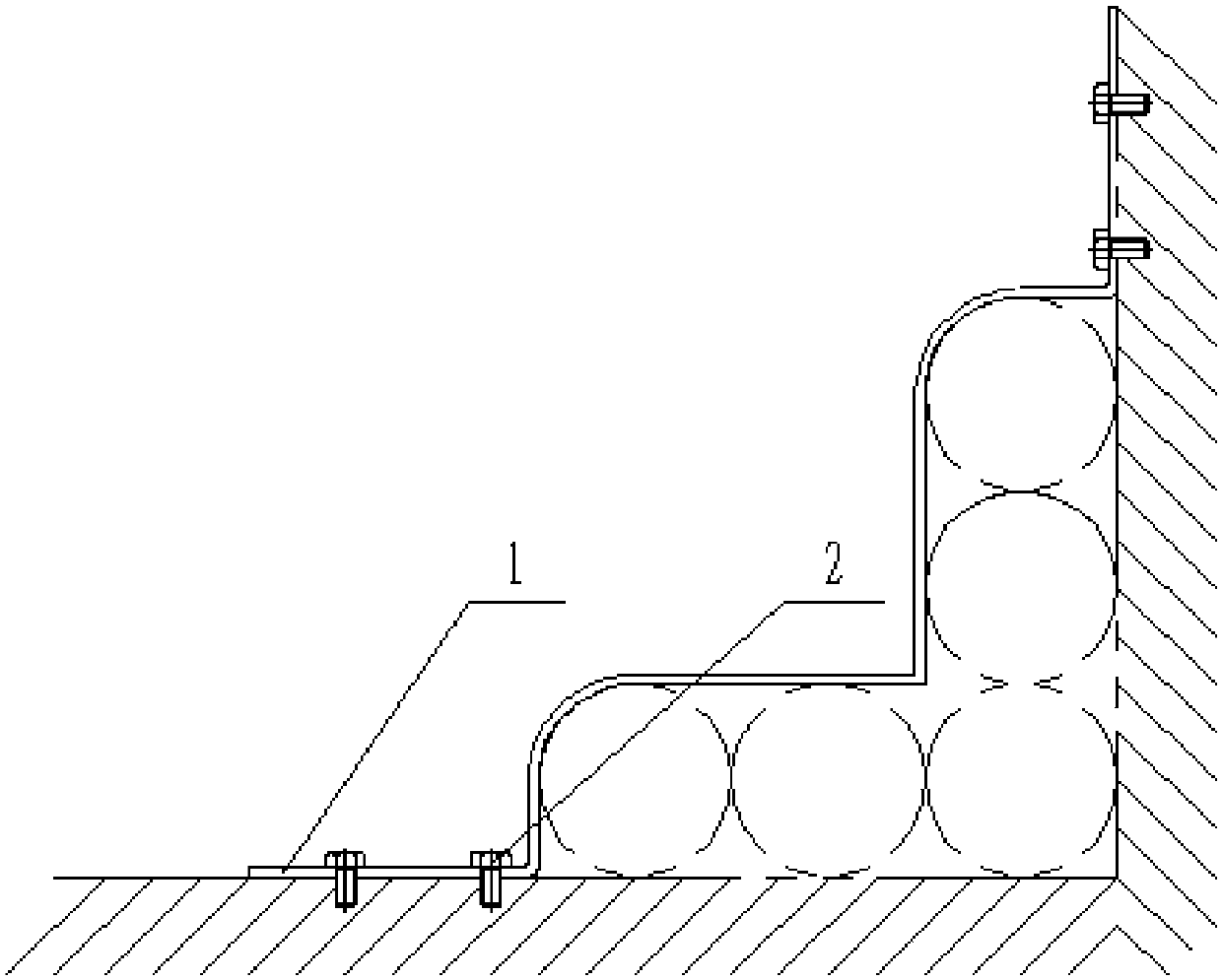
[0011] Specific embodiments of the invention will be described in detail below in conjunction with the accompanying drawings.

[0012] Right-angle clamps, such as figure 1 As shown, it includes the clamp (1) and the bolt (2). The two ends of the clamp (1) are fixed at the corner of the wall by the bolt (2). The angle between the clamp (1) and the corner of the wall is 90 degrees. Keep consistent, so that the lines are arranged more neatly and beautifully, and the two ends close to the spiral (2) are respectively bent arc angles, which are more suitable for the arc of the lines.

[0013] An embodiment of the present invention has been described in detail above, but the content described is only a preferred embodiment of the present invention and cannot be considered as limiting the implementation scope of the present invention. All equivalent changes and improvements made according to the application scope of the present invention shall still belong to the scope covered by the...


PUM


Abstract

The invention creatively provides a right-angled wire clamping clip, including a wire clip and bolts. The wire clip fixes a flat cable at the corner of the wall through the bolts. The fixture has thecharacteristics of stable structure and simple clamping, and can clamp multiple rows of pipelines and improve the clamping efficiency.

Description

technical field [0001] The invention belongs to the technical field of clamps, and in particular relates to a right-angle clamp for clamping wires. Background technique [0002] Regardless of whether industrial and mining enterprises or buildings install pipeline fittings, they will use clamps to fix the lines, but each line is fixed with a clamp, which is time-consuming and laborious. Contents of the invention [0003] The problem to be solved by the invention is to provide a right-angle clip for clamping wires, which has a stable structure and simple clamping, can clamp multiple rows of lines, and improves clamping efficiency. [0004] In order to solve the above-mentioned technical problems, the technical solution adopted by the present invention is: a right-angle wire clip, including a wire clip and a bolt, the wire clip is fixed at the corner of the wall by the bolt, and the middle angle of the wire clip is 90° degrees, and the end close to the helix is ​​the arc ang...

Claims


Application Information

Patent Timeline
IPC IPC(8): H02G1/02
Inventor 黄莉萍
Owner 绍兴中普防雷科技有限公司
Features
  • Generate Ideas
  • Intellectual Property
  • Life Sciences
  • Materials
  • Tech Scout
  • Unparalleled Data Quality
  • Higher Quality Content
  • 60% Fewer Hallucinations
Learn More