
A method and apparatus for decoding information delivered by a light source

A technology of light source and image sensor, applied in the field of optical information, can solve the problems of unsatisfactory stability and reliability, small delay, affecting the shooting effect, etc.

Active Publication Date: 2019-06-25
SHAANXI WHYHOW INFORMATION TECH CO LTD
View PDF10 Cites 3 Cited by
  • Summary
  • Abstract
  • Description
  • Claims
  • Application Information

AI Technical Summary

Problems solved by technology

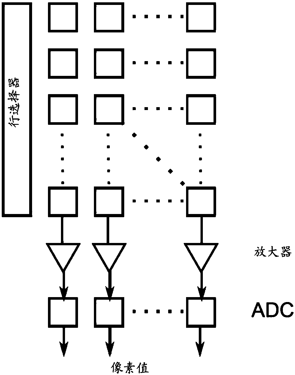
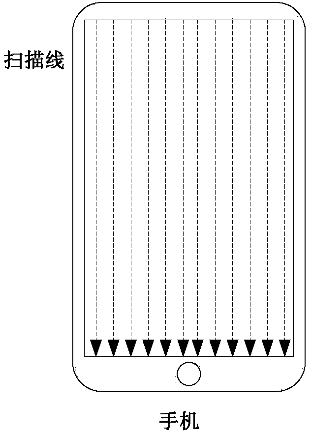
Therefore, the entire CMOS image sensor array is actually exposed row by row (in some cases, the CMOS image sensor array may also use the method of exposing multiple rows at a time), which leads to a small time delay between each row
Due to the small time delay, when the light source flickers at a certain frequency, some undesired stripes will appear on the image captured by the CMOS imaging device, which will affect the shooting effect
[0004] People have found that it is theoretically possible to use the stripes on the image taken by the CMOS imaging device to transmit information (similar to a barcode), and try to transmit as much information as possible through the stripes, but this usually requires making the CMOS imaging device and the light source as close as possible. close, and preferably always at roughly fixed distances, and also requires fine time synchronization, precise recognition of the boundaries of individual fringes, accurate detection of the width of individual fringes, etc., so in practice its stability and Unsatisfactory reliability and not widely used

Method used


Image

  • A method and apparatus for decoding information delivered by a light source
  • A method and apparatus for decoding information delivered by a light source
  • A method and apparatus for decoding information delivered by a light source

Examples


Embodiment Construction

[0049] In order to make the object, technical solution and advantages of the present invention clearer, the present invention will be further described in detail below through specific embodiments in conjunction with the accompanying drawings.

[0050]One embodiment of the present invention relates to an optical communication device capable of transmitting different information by emitting different lights. The optical communication device is also referred to herein as an "optical tag", and the two may be used interchangeably throughout this application. The optical communication device includes a light source and a controller, the controller is configured to control the light source to work in two or more modes, the two or more modes include a first mode and a second mode, wherein, in In the first mode, the property of the light emitted by the light source changes at a first frequency to convey the first information; in the second mode, the property of the light emitted by th...


PUM


Abstract

The invention discloses a method for decoding information transmitted by a light source. The light source is configured to work in at least two modes. In different modes, when the CMOS image sensor shoots the light source, the obtained image of the light source presents different predetermined appearances to represent different data, and the method comprises the following steps: continuously shooting the light source through a CMOS imaging device; obtaining a plurality of frames of continuous images of the light source; For each frame of image of the light source, respectively extracting a starting part and an ending part of the image; analyzing the extracted starting part and ending part to determine data represented by each starting part and ending part; And performing a data removal operation on the data represented by the ending part of each frame of image and the data represented by the starting part of the next frame of image following the ending part of each frame of image to determine a data sequence transmitted by the light source.

Description

technical field [0001] The invention belongs to the technical field of optical information, and more specifically relates to a method for decoding information transmitted by a light source. Background technique [0002] Barcodes and QR codes have been widely adopted to encode information. When these barcodes and QR codes are scanned with specific equipment or software, the corresponding information will be recognized. However, the recognition distance of barcodes and QR codes is very limited. For example, for a two-dimensional code, when scanning it with a mobile phone camera, the mobile phone must usually be placed in a relatively close distance, which is usually only about 15 times the width of the two-dimensional code. Therefore, for long-distance identification (for example, a distance equivalent to 200 times the width of a two-dimensional code), barcodes and two-dimensional codes are usually not possible, or very large barcodes and two-dimensional codes must be custom...

Claims


Application Information

Patent Timeline
Patent Type & Authority Applications(China)
IPC IPC(8): H04N5/374H04N5/378H04N5/235H04N5/232
CPCH04B10/116G06V10/10H04N23/60H04N23/70H04N25/44H04N25/76H04N25/78
Inventor 方俊牛旭恒
Owner SHAANXI WHYHOW INFORMATION TECH CO LTD
Learn More