Automobile back door built-in tooling structure

An automotive back door, built-in technology, used in metal processing, manufacturing tools, metal processing equipment, etc., can solve the problems affecting customers' evaluation of the appearance of the model, high quality parts requirements, and different adjustment states of the back door. The effect of shortening manual assembly adjustment man-hours, reducing parts accuracy requirements, and reducing the amount of manual adjustment

Pending Publication Date: 2019-06-28
DFSK MOTOR LTD CHONGQING BRANCH CO
View PDF0 Cites 2 Cited by
  • Summary
  • Abstract
  • Description
  • Claims
  • Application Information

AI Technical Summary

Problems solved by technology

[0002] The rear face of a car is the key area for the subjective evaluation of the vehicle's appearance quality, and the most important part of the rear face area is the cooperation between the back door and the side wall, the side clearance and the taillights. At present, most models are limited by the accuracy of the back door parts and the assembly scheme. As a result, the gap between the back door and the side wall, the back door and the taillight is uneven, and the surface difference is uneven, which directly affects the customer's evaluation of the appearance of the model.
At present, most of the assembly of the back door is completed through online manual adjustment, or by tightening the tolerance requirements of the parts. The traditional two methods have labor intensive labor, long hours, high-quality parts, and inconsistent tooling standards. The cumulative error is large, resulting in back door The door installation and adjustment state is different, the stability is poor, and the appearance is affected

Method used


Image

  • Automobile back door built-in tooling structure
  • Automobile back door built-in tooling structure
  • Automobile back door built-in tooling structure

Examples


Embodiment

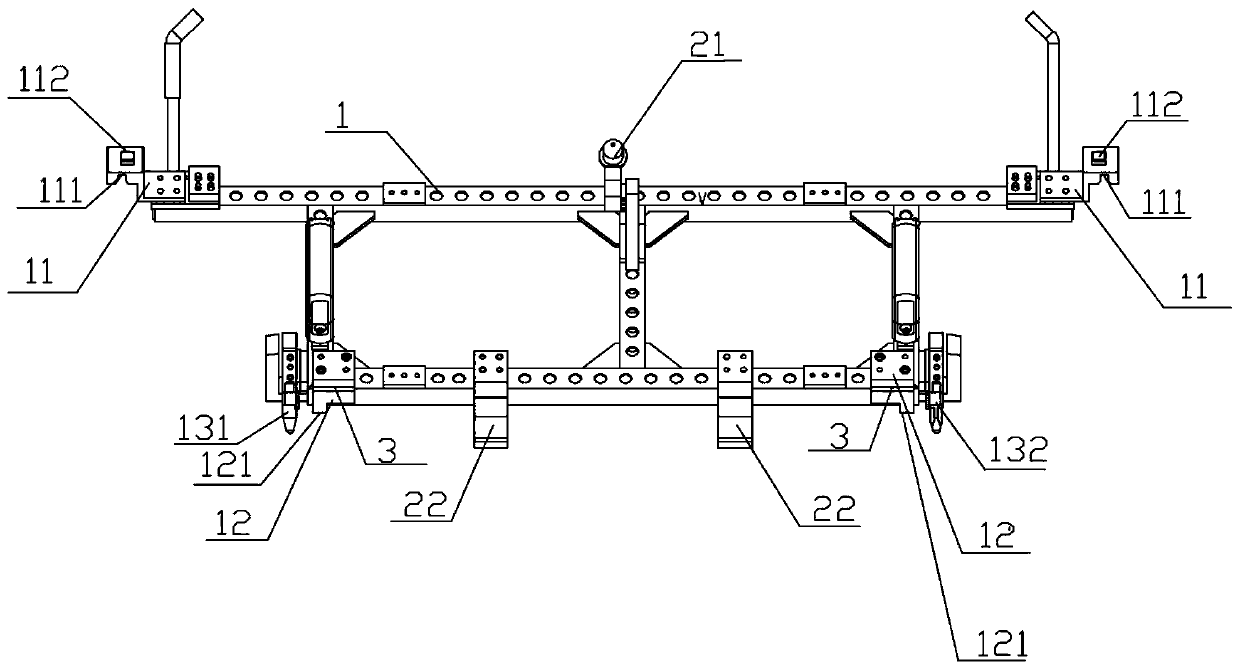
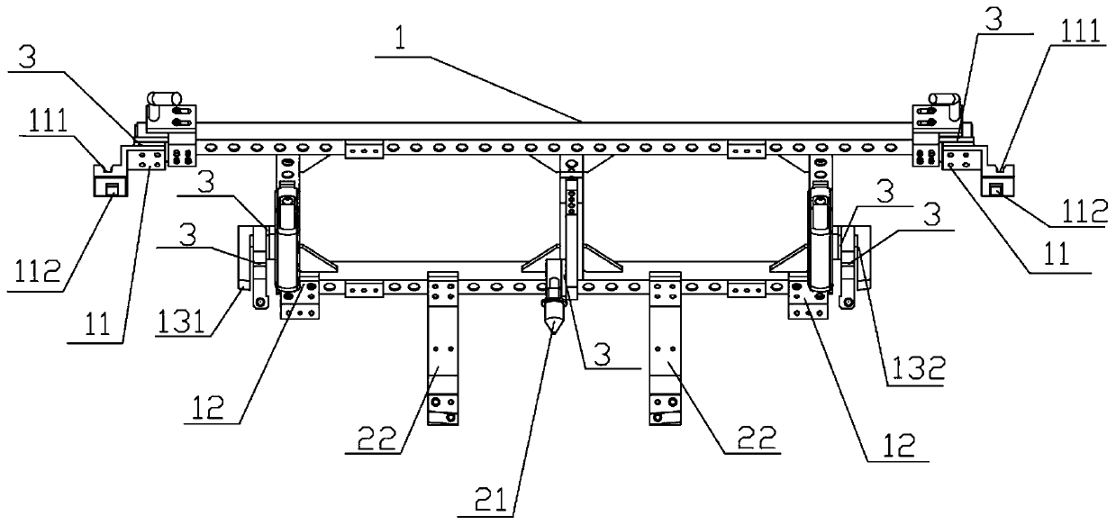
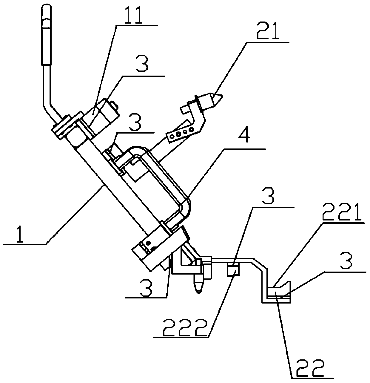
[0030] Such as figure 1 , figure 2 , image 3 As shown, a vehicle back door built-in tooling structure includes a tooling frame 1; the tooling frame 1 is provided with a first positioning assembly for positioning with the vehicle body and a second positioning assembly for positioning with the back door;

[0031] Wherein, the second positioning assembly includes the back door Y direction positioning pin 21 fixed on the width direction of the tooling frame 1 and the back door Z direction positioning block 22 fixed on the tooling frame 1 length direction, the back door Y direction positioning pin 21 and the back door The corresponding Y-direction positioning holes are connected, and the Z-direction positioning block 22 of the back door includes a Z-direction positioning surface 221 of the back door, and the Z-direction positioning surface 221 of the back door is attached to the corresponding reference surface on the back door; perpendicular to each other.

[0032] Specificall...


PUM


Abstract

The invention discloses an automobile back door built-in tooling structure. The tooling structure comprises a tooling framework. The tooling framework is provided with a first positioning assembly matched with an automobile body for positioning and a second positioning assembly matched with a back door for positioning. The second positioning assembly comprises a back door Y-direction positioning pin fixed to the width direction of the tooling framework and back door Z-direction positioning blocks fixed to the length direction of the tooling framework. The back door Y-direction positioning pinis connected with a corresponding Y-direction positioning hole corresponding in the back door. Each back door Z-direction positioning block comprises a back door Z-direction positioning surface attached to a corresponding reference surface of the back door, wherein the Y-direction is perpendicular to the Z-direction. Through the automobile back door built-in tooling structure, the back door and the automobile door are assembled. The automobile back door built-in tooling structure ensures that the gap surface differences between the back door and a sidewall and between a tail lamp and the sideface are good. Meanwhile, the part accuracy of a back door assembly can be reduced, the part machining cost can be reduced, and the online manual assembly and adjustment time is shortened.

Description

technical field [0001] The invention relates to the field of automobiles, in particular to an automobile back door built-in tooling structure. Background technique [0002] The rear face of a car is the key area for the subjective evaluation of the vehicle's appearance quality, and the most important part of the rear face area is the cooperation between the back door and the side wall, the side clearance and the taillights. At present, most models are limited by the accuracy of the back door parts and the assembly plan. As a result, the gap between the back door and the side wall, the back door and the taillight is uneven, and the surface difference is uneven, which directly affects the customer's evaluation of the appearance of the model. At present, most of the assembly of the back door is completed through online manual adjustment, or by tightening the tolerance requirements of the parts. The traditional two methods have labor intensive labor, long hours, high-quality par...

Claims


Application Information

Patent Timeline
Patent Type & Authority Applications(China)
IPC IPC(8): B23P19/00
Inventor 李成杰张正源刘昌东
Owner DFSK MOTOR LTD CHONGQING BRANCH CO
Why Eureka
Try Eureka