Bonding joint

A technology of glue joints and glue grooves, applied in the direction of pipes/pipe joints/fittings, non-detachable pipe connections, passing elements, etc., can solve the defects of glue layer, affect the connection strength of glue layer, and the connection strength of glue joints needs to be improved and other problems, to achieve the effect of consistent thickness and improved connection strength

Inactive Publication Date: 2019-06-28
皓宇智能有限公司
View PDF8 Cites 3 Cited by
  • Summary
  • Abstract
  • Description
  • Claims
  • Application Information

AI Technical Summary

Problems solved by technology

In order to improve the connection strength of the joint in the existing glued joints, generally two workpieces are placed into two filaments or spacers to control the thickness of the glue layer. However, because the filaments or gaskets are embedded in the glue layer, the There are defects in the adhesive layer, which affect the connection strength of the adhesive layer
[0003] Therefore, the connection strength of existing glued joints needs to be improved

Method used


Image

  • Bonding joint
  • Bonding joint
  • Bonding joint

Examples


no. 1 example

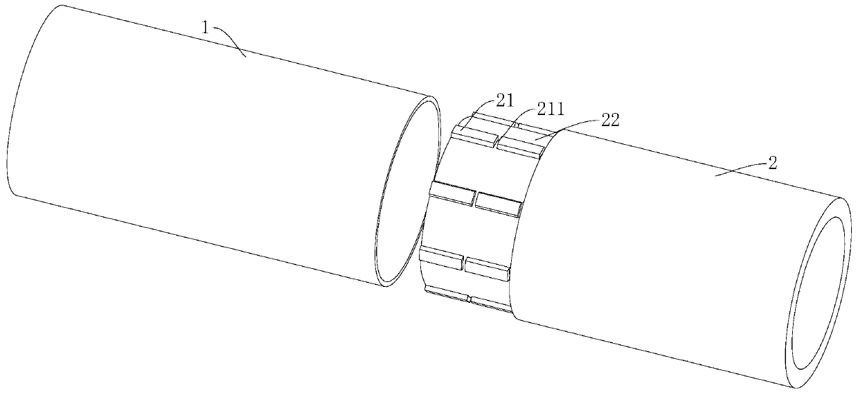
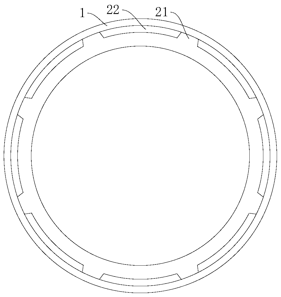
[0029] see Figure 1-Figure 3 , the adhesive joint of the present invention includes an inner pipe 2 and an outer pipe 1, the inner pipe 2 is sleeved on the outer pipe 1, and one of the inner pipe 2 and the outer pipe 1 is provided with several guide ribs 21, and the guide ribs 21 Adapted to abut against the other so that the axis of the inner tube 2 is collinear with the axis of the outer tube 1 . Adhesive grooves 22 are formed between adjacent guide ribs 21 , and the adhesive grooves 22 contain an adhesive, which is used to bond and fix the inner tube 2 and the outer tube 1 . A plurality of guide ribs 21 are provided on the inner tube 2 or the outer tube 1, so that when the outer tube 1 is socketed on the inner tube 2, the guide ribs 21 can be quickly positioned and guided, that is, quick installation is realized. And, because the guide rib 21 abuts against the outer wall surface of the inner tube 2, or the guide rib 21 abuts against the inner wall surface of the outer tube...

no. 2 example

[0035] Figure 4-Figure 5 Shows the glued joint of the second embodiment of the present invention, the second embodiment provides the glued joint including the first embodiment, which is different from the first embodiment in that the outer contour of the guide rib 21 is a ring structure, Several guide ribs 21 are arranged at intervals along the axis of the inner tube 2 or the outer tube 1 . It can be understood that after the guide ribs 21 abut against the inner wall of the inner tube 2 or the outer tube 1, each guide rib 21 can prevent the adhesive from migrating on a large scale, thereby preventing the adhesive from freeing from the glue groove 22 and entering the inner tube 2 or the outer tube 1. Inside of tube 1, and the blocking effect is better. In this embodiment, preferably, several guide ribs 21 are arranged at intervals along the axis of the inner tube 2 .

[0036] Preferably, the guide rib 21 is provided with a second water channel 212 , the second water channel ...


PUM


Abstract

The invention discloses a bonding joint. The bonding joint comprises an inner pipe and an outer pipe, wherein the inner pipe is sleeved with the outer pipe, one of the inner pipe and the outer pipe isprovided with a plurality of guide ribs, and the guide ribs are suitable for abutting against the other pipe, so that the axis of the inner pipe and the axis of the outer pipe are collinear. Bondinggrooves are formed between adjacent guide ribs, bonding material is contained in the bonding grooves, and the bonding material is used for bonding and fixing the inner pipe and the outer pipe. Throughthe plurality of guide ribs on the inner pipe or the outer pipe, when the outer pipe sleeves the inner pipe, the guide ribs can quickly position the pipes and guide the pipes, so that quick installation is realized. In addition, the bonding grooves of the bonding joint can accommodate equivalent bonding material, the guide ribs can prevent the bonding material from moving on a large scale, so that the thickness of the bonding material in each bonding groove is consistent, and the connection strength of the bonding joint is greatly improved.

Description

technical field [0001] The invention relates to the technical field of joints, in particular to adhesive joints. Background technique [0002] Glued joints (the definition of glued joints: that is, joints made of materials such as rubber, plastic or composite materials; and, the joints of glued joints are fixed with adhesives, and a glue layer is formed when the adhesives are cured.) Due to It has the characteristics of light weight, low cost, easy installation, and small stress concentration at the glued joint (the place where the joints are connected with an adhesive, that is, the glued joint), and has a wide range of applications. Moreover, since the glued joint uses an adhesive (ie, glue layer) with good adhesive performance and good elasticity as the connecting material, the connection strength of the glued joint is affected by many factors. For example: the thickness of the adhesive layer, whether the thickness of the adhesive layer is uniform, etc. will affect the co...

Claims


Application Information

Patent Timeline
Patent Type & Authority Applications(China)
IPC IPC(8): F16L13/10
Inventor 郑子衡
Owner 皓宇智能有限公司
Why Eureka
Try Eureka