Flashlight

A flashlight and tube body technology, applied in the field of lighting, can solve the problems of low withstand current of the on-off switch, difficult control of production quality, and limited product power, and achieve high-frequency flickering, wide operating voltage, and high-power output. Effect

Pending Publication Date: 2019-06-28
SHENZHEN LANGHENG ELECTRICAL
View PDF0 Cites 2 Cited by
  • Summary
  • Abstract
  • Description
  • Claims
  • Application Information

AI Technical Summary

Problems solved by technology

[0002] The common flashlights in the existing market generally use a single barrel, and the mechanical switch is set at the tail of the flashlight and is only used as a current on-off switch. The function operation is single, and the on-off switch can withstand a small current, which limits the power of the product.
Another kind of flashlight uses two barrels or a single barrel to set multiple conductive paths. Two or more switches can be placed at the tail of the flashlight to achieve more functional operations, but the power of the flashlight is still limited by the tail mechanism. The switch withstands the current limit, the power is small and the process is complicated, the production quality is difficult to control, the production cost is high, and the reliability of the product is reduced
Moreover, for a flashlight with a single barrel and a single or two switch controls at the tail, the current control circuit unit driven by the light source is at the tail of the flashlight, and the off time of the pulse width modulation supplies power to the tail circuit. When the flashlight is lit with a low or high current, the tail power switch is turned off for a short time, causing insufficient power supply to the tail circuit, resulting in adverse phenomena such as the flashlight being extinguished
This type of flashlight uses pulse width modulation to drive the light source, the light output is discontinuous, and the light source will flicker with the pulse width current modulation at the tail, which is easy to make people's eyes tired and cannot be used in occasions that require high light sources such as photography supplementary light. use

Method used


Image

  • Flashlight
  • Flashlight
  • Flashlight

Examples


Embodiment Construction

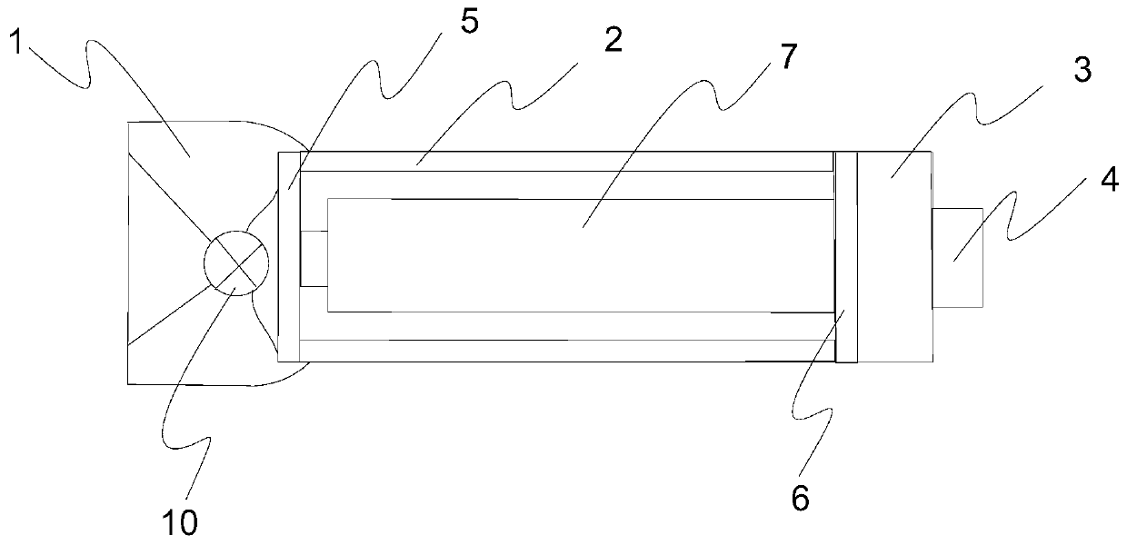
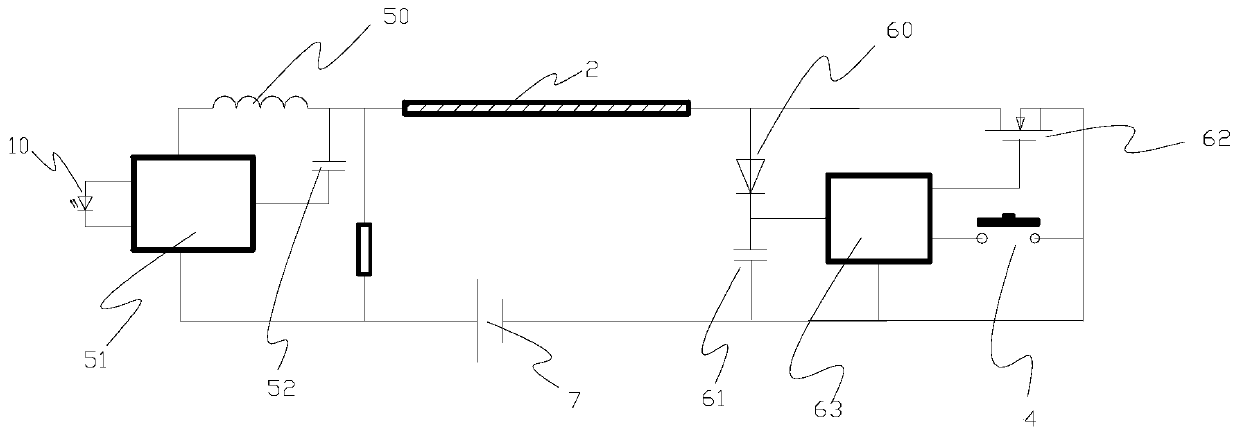
[0021] In order to more clearly illustrate the purpose, technical solutions and advantages of the embodiments of the present invention, the present invention will be further described below in conjunction with the accompanying drawings and embodiments, and a clear and complete description will be made. Obviously, the described embodiments are the embodiment of the present invention. Some examples, but not all examples. Based on the embodiments of the present invention, all other embodiments obtained by persons of ordinary skill in the art without making creative efforts belong to the protection scope of the present invention. In addition, directional terms mentioned in the present invention, such as "upper", "lower", "front", "rear", "left", "right", "inner", "outer", etc., are for reference only The directions shown in the attached drawings and the direction terms used are for better and clearer description and understanding of the present invention, rather than indicating or...


PUM


Abstract

The invention relates to a flashlight which includes a lamp holder, a barrel body, a lamp tail and a switch are arranged on the lamp holder, the barrel body or the lamp tail, wherein the conducting two ends of the barrel body are corresponding to single barrel body connected with the lamp holder and the lamp tail; a light source, a first control circuit board electrically connected with the lightsource and controlling light output of the light source are arranged inside the lamp holder; a second control circuit board electrically connected with the switch is arranged inside the lamp tail; a first diode and a second diode that are mutually electrically conducted, a first capacitor, a field-effect tube and a first MCU unit are arranged on the second control circuit board; a battery is further arranged inside the barrel body; the first control circuit board and the second control circuit board are correspondingly connected with two poles of the battery, and are electrically connected through the barrel body. According to the invention, the operation signal of the switch is converted into a modulating signal, then the modulated control information data is superposed on a primary current, then single barrel body transmission is adopted, so that the light source can be driven by a large current, large power output and wide operating voltage are realized, and high frequency flicker of the light source cannot be caused.

Description

technical field [0001] The invention relates to the field of illumination, in particular to a flashlight capable of driving a light source with high current, high power output, wide operating voltage, and not causing high-frequency flickering of the light source. Background technique [0002] The common flashlights in the existing market generally use a single barrel, and the mechanical switch is set at the tail of the flashlight and is only used as a current on-off switch. The function and operation are single, and the on-off switch can withstand a small current, which limits the power of the product. Another kind of flashlight uses two barrels or a single barrel to set multiple conductive paths. Two or more switches can be placed at the tail of the flashlight to achieve more functional operations, but the power of the flashlight is still limited by the tail mechanism. The switch is limited by the withstand current, the power is small, the process is complicated, the produc...

Claims


Application Information

Patent Timeline
Patent Type & Authority Applications(China)
IPC IPC(8): F21L4/00F21V23/00F21V23/04F21Y115/10
Inventor 岑亮蔡星海陈海彬
Owner SHENZHEN LANGHENG ELECTRICAL
Why Eureka
Try Eureka