
Water tank assembly, air conditioner humidifier and air conditioner

A humidifier and water tank technology, applied in air humidification systems, air conditioning systems, heating methods, etc., can solve the problems of inconvenient maintenance, complex structure and high cost, and achieve the effects of convenient maintenance, simple structure and low cost

Pending Publication Date: 2019-06-28
GD MIDEA HEATING & VENTILATING EQUIP CO LTD +1
View PDF0 Cites 1 Cited by
  • Summary
  • Abstract
  • Description
  • Claims
  • Application Information

AI Technical Summary

Problems solved by technology

[0002] In the related art, the water supply device of the second water tank of the water tank assembly is a water pump with an external power source, and the water in the first water tank is pumped into the second water tank through the action of the water pump. At the same time, in order to ensure that there is a certain amount of water in the second water tank, a The water level monitoring device is used to detect the water level in the second water tank. Both the water pump and the water level detection device are connected to the control circuit, which has a complicated structure, high cost and inconvenient maintenance

Method used


Image

  • Water tank assembly, air conditioner humidifier and air conditioner
  • Water tank assembly, air conditioner humidifier and air conditioner
  • Water tank assembly, air conditioner humidifier and air conditioner

Examples


Embodiment Construction

[0054]Embodiments of the present invention are described in detail below, examples of which are shown in the drawings, wherein the same or similar reference numerals designate the same or similar elements or elements having the same or similar functions throughout. The embodiments described below by referring to the figures are exemplary only for explaining the present invention and should not be construed as limiting the present invention.

[0055] A water tank assembly 100 according to an embodiment of the present invention is described below with reference to the accompanying drawings.

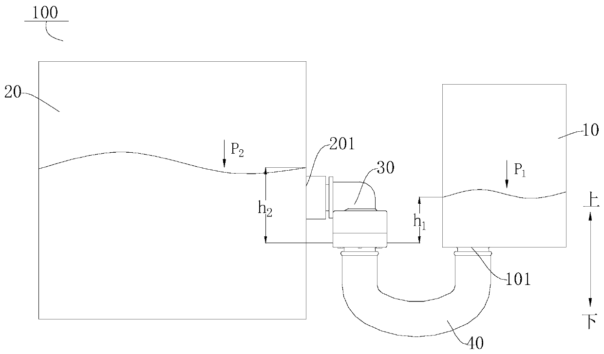
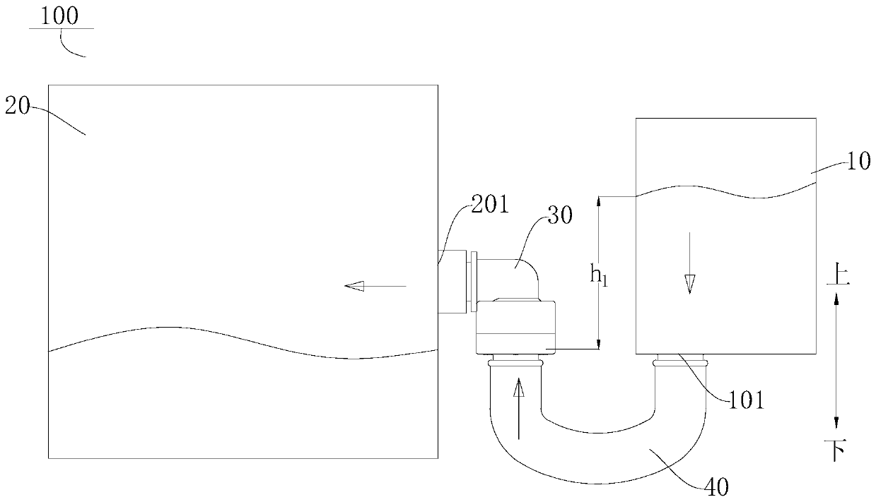
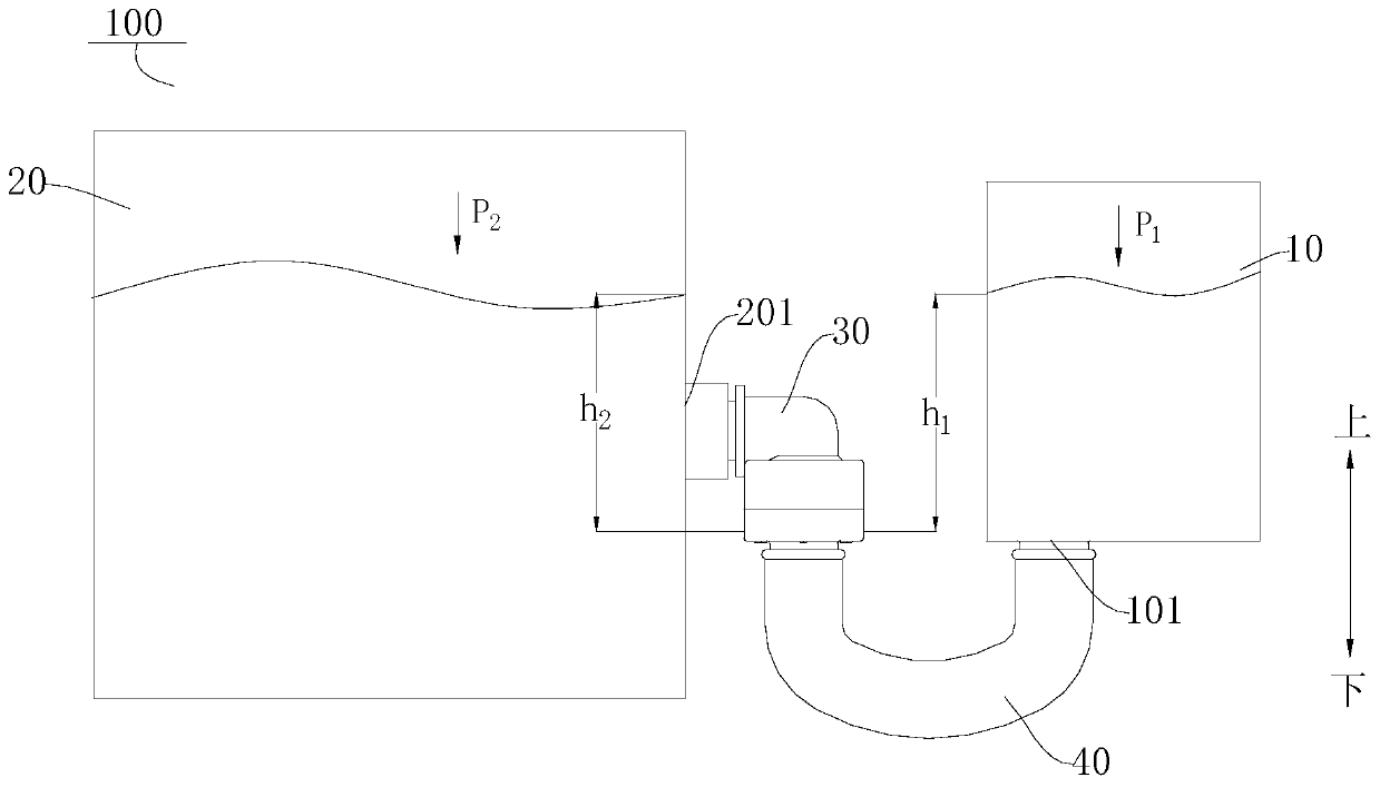
[0056] refer to figure 1 As shown, the water tank assembly 100 according to the embodiment of the present invention may include: a first water tank 10, a second water tank 20 and a one-way valve 30, the first water tank 10 has a water outlet 101, and the first water tank 10 communicates with the atmosphere. For example, a ventilation hole may be provided on the top of the first water tank ...


PUM


Abstract

The invention discloses a water tank assembly, an air conditioner humidifier and an air conditioner. The water tank assembly comprises a first water tank, a second water tank and a one-way valve. Thefirst water tank is provided with a water outlet, and communicates with the atmosphere; the second water tank is provided with a water inlet, and the gas pressure in the second water tank is variable.The one-way valve comprises a valve seat and a valve core, wherein a valve cavity is formed in the valve seat; the valve seat is provided with a first interface and a second interface which communicate with the valve cavity; the first interface is connected with the water outlet; the second interface is connected with the water inlet; and the valve core is movably arranged in the valve cavity andis positioned between the first interface and the second interface. When the acting force F borne by the valve core is greater than 0, the valve core moves to unidirectionally guide the valve cavityin a direction from the first interface to the second interface, and the first water tank can automatically supply water to the second water tank. According to the water tank assembly, water in the second water tank cannot flow back to the first water tank, and meanwhile, the first water tank can automatically supply water to the second water tank without external power.

Description

technical field [0001] The invention relates to the field of air treatment equipment, in particular to a water tank assembly, an air conditioner humidifier and an air conditioner. Background technique [0002] In the related art, the water supply device of the second water tank of the water tank assembly is a water pump with an external power source, and the water in the first water tank is pumped into the second water tank through the action of the water pump. At the same time, in order to ensure that there is a certain amount of water in the second water tank, a The water level monitoring device is used to detect the water level in the second water tank. Both the water pump and the water level detecting device are connected with the control circuit, and the structure is complicated, the cost is high, and the maintenance is inconvenient. Contents of the invention [0003] The present invention aims to solve at least one of the technical problems existing in the prior art....

Claims


Application Information

Patent Timeline
Patent Type & Authority Applications(China)
IPC IPC(8): F24F1/037F24F6/00F24F6/10F16K31/122F16K1/32
Inventor 阮涛潘柏江罗彬
Owner GD MIDEA HEATING & VENTILATING EQUIP CO LTD
Learn More