
Both eye imaging detection device and detection method

A technology of binocular imaging and detection device, which is applied in measurement devices, radiation pyrometry, optical radiation measurement, etc., can solve the problems of low detection accuracy and single detection function, and achieve the effect of scalability.

Active Publication Date: 2021-05-25
深圳市行知达科技有限公司
View PDF0 Cites 0 Cited by
  • Summary
  • Abstract
  • Description
  • Claims
  • Application Information

AI Technical Summary

Problems solved by technology

[0004] The purpose of the present invention is to provide a binocular imaging detection device and detection method, aiming to solve the technical problems of low detection accuracy and single detection function of electric power facility detection equipment in the prior art

Method used


Image

  • Both eye imaging detection device and detection method
  • Both eye imaging detection device and detection method
  • Both eye imaging detection device and detection method

Examples


Embodiment Construction

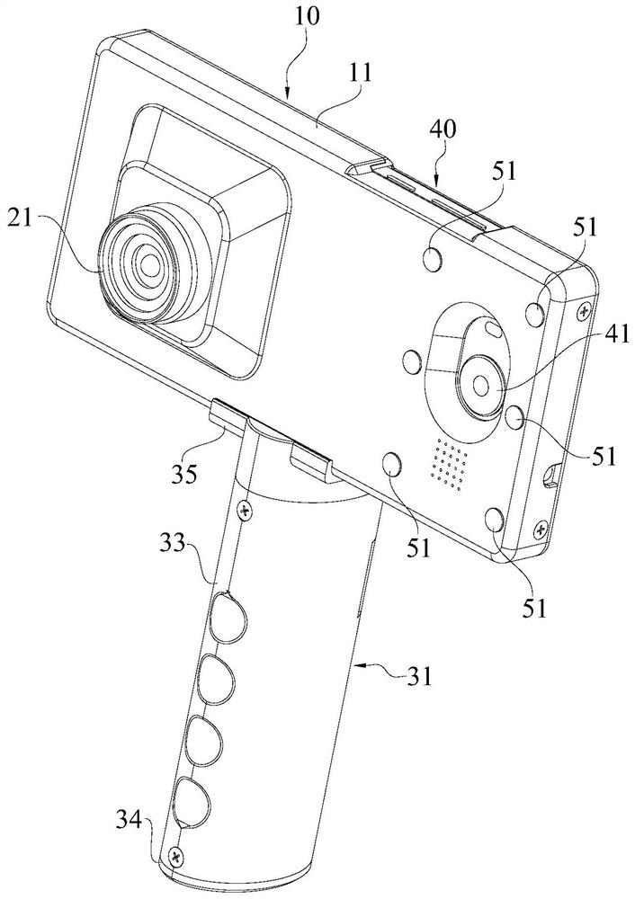
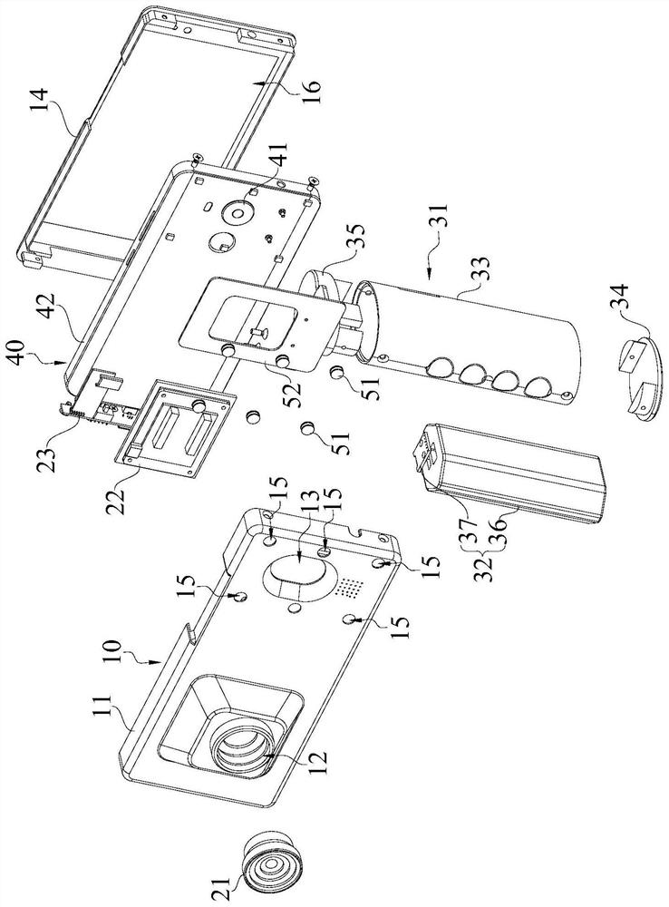
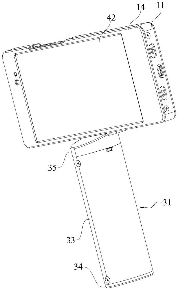
[0041] Embodiments of the present invention are described in detail below, examples of which are shown in the drawings, wherein the same or similar reference numerals designate the same or similar elements or elements having the same or similar functions throughout. Attached below by reference Figure 1-7 The described embodiments are exemplary and are intended to explain the present invention, but should not be construed as limiting the present invention.

[0042] In describing the present invention, it should be understood that the terms "length", "width", "upper", "lower", "front", "rear", "left", "right", "vertical", The orientation or positional relationship indicated by "horizontal", "top", "bottom", "inner", "outer", etc. are based on the orientation or positional relationship shown in the drawings, and are only for the convenience of describing the present invention and simplifying the description, rather than Nothing indicating or implying that a referenced device or e...


PUM


Abstract

The invention belongs to the technical field of power facility detection equipment, and in particular relates to a binocular imaging detection device and detection method, including a housing assembly, an infrared detection module and a terminal, the infrared detection module includes an optical lens and an infrared detection module, and the housing assembly It includes an assembly shell, the assembly shell is provided with a first light hole and a second light hole on the same side, the optical lens is fixedly installed on the assembly shell and is facing the first light hole, and the infrared detection module is arranged on the assembly The housing is facing the first light hole. The terminal includes a camera, an image processing module and a terminal body. The terminal body is accommodated in the assembly shell. The camera is fixedly installed on the outer wall of the terminal body and is set facing the second light hole. , the image processing module is arranged in the terminal body and is electrically connected with the infrared detection module. In this way, the image processing module can establish a one-to-one mapping relationship between the visible light image and the infrared image, and locate the fault point in the power facility.

Description

technical field [0001] The invention belongs to the technical field of electric facility detection equipment, and in particular relates to a binocular imaging detection device and a detection method. Background technique [0002] Power facilities are generally composed of cabinets, circuit breakers, protection devices, monitoring devices, electric energy meters, and other secondary components. They are characterized by many components, complex circuits, complex detection, and easy missed detection. At present, power facility detection instruments based on infrared thermal imagers are used more and more frequently. Infrared thermal imagers have the characteristics of quickly capturing heat-sensitive areas, and imaging is not affected by light and climate. [0003] However, thermal imaging cameras have low image resolution and low positioning accuracy. They can only detect virtual connection faults, and cannot troubleshoot faults such as missing and wrong connections of compon...

Claims


Application Information

Patent Timeline
Patent Type & Authority Patents(China)
IPC IPC(8): G01J5/00G01C11/04G06K9/00G06K9/20
Inventor 王书付宗德祥赵耀贾冬庆杨德明
Owner 深圳市行知达科技有限公司
Learn More