Feed-through voltage compensation circuit and liquid crystal display device

A technology of liquid crystal display device and feed-through voltage, which is applied to static indicators, instruments, etc., can solve problems affecting pixel charging, etc., and achieve the effects of reducing electrostatic discharge, saving area, and reducing cross-line problems of different signals

Active Publication Date: 2019-06-28
XIANYANG CAIHONG OPTOELECTRONICS TECH CO LTD
View PDF5 Cites 2 Cited by
  • Summary
  • Abstract
  • Description
  • Claims
  • Application Information

AI Technical Summary

Problems solved by technology

[0005] This method can reduce the effect of △Vp, but it will affect the pixel charging

Method used


Image

  • Feed-through voltage compensation circuit and liquid crystal display device
  • Feed-through voltage compensation circuit and liquid crystal display device
  • Feed-through voltage compensation circuit and liquid crystal display device

Examples


Embodiment 1

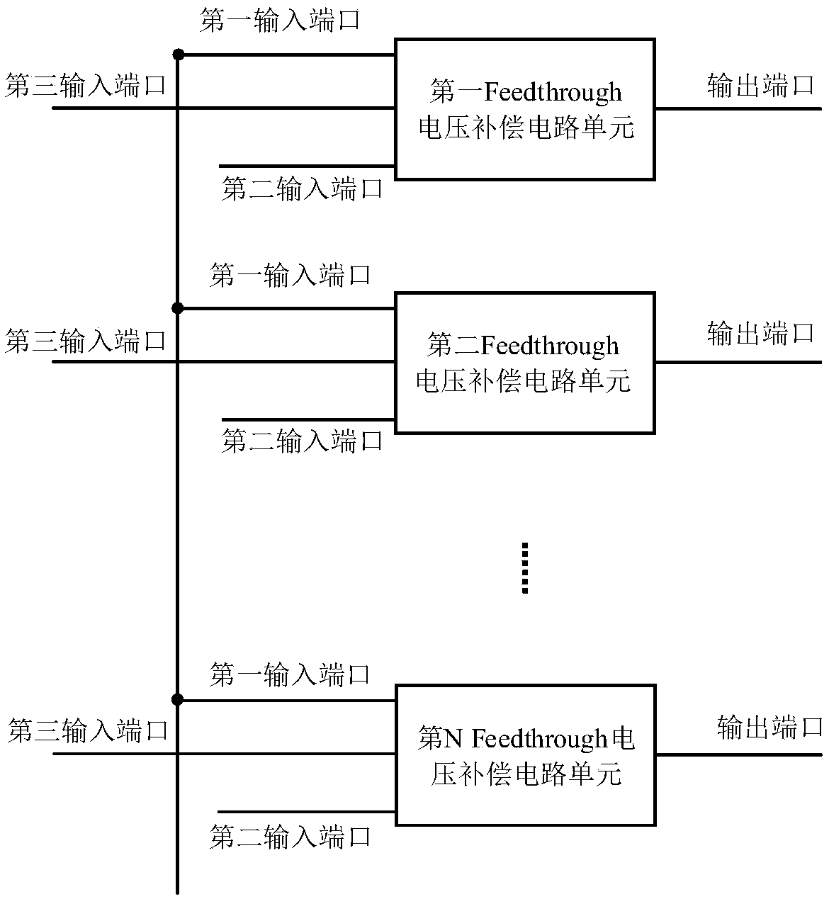
[0047] See image 3 , image 3 A schematic diagram of a Feedthrough voltage compensation circuit provided by an embodiment of the present invention. The Feedthrough voltage compensation circuit is applied to a liquid crystal display device, and includes a plurality of feedthrough voltage compensation circuit units, and the feedthrough voltage compensation circuit units are used to generate a feedthrough voltage compensation signal of a scanning line to be compensated; wherein,

[0048] Each of the feedthrough voltage compensation circuit units includes a first input port, a second input port, and a third input port; wherein, the first input port inputs a turn-on voltage (Vgh), and the second input port Inputting a cut-off voltage (Vgl), the third input ports respectively input the scanning voltages of the scanning lines to be compensated.

[0049] Further, the first input port of each feedthrough voltage compensation circuit unit is electrically connected to a first direct c...

Embodiment 2

[0055] See Figure 4 , Figure 4 A schematic diagram of another Feedthrough voltage compensation circuit provided by an embodiment of the present invention. On the basis of the above embodiments, another Feedthrough voltage compensation circuit proposed by the present invention will be described in detail.

[0056] Specifically, the Feedthrough voltage compensation circuit may include N Feedthrough voltage compensation circuit units, each Feedthrough voltage compensation circuit unit corresponds to one scanning drive circuit unit, and is used to generate a Feedthrough voltage that is similar in magnitude to the voltage of the scanning line to be compensated compensation signal.

[0057] The first input port of each Feedthrough voltage compensation circuit unit is connected to form the first input port of the Feedthrough voltage compensation circuit, wherein the first input port of the Feedthrough voltage compensation circuit is electrically connected to the first DC source; ...

Embodiment 3

[0061] See Figure 5 , Figure 5 Another schematic diagram of a Feedthrough voltage compensation circuit provided by an embodiment of the present invention. This embodiment describes in detail another Feedthrough voltage compensation circuit on the basis of the above embodiments.

[0062] Specifically, the circuit may include: N Feedthrough voltage compensation circuit units, each Feedthrough voltage compensation circuit unit corresponds to one scanning drive circuit unit, and is used to generate a Feedthrough voltage compensation signal that is similar in magnitude to the voltage of the scanning line to be compensated .

[0063] The first input port of each Feedthrough voltage compensation circuit unit is connected to form the first input port of the Feedthrough voltage compensation circuit, wherein the first input port of the Feedthrough voltage compensation circuit is electrically connected to the first DC source; each Feedthrough voltage compensation circuit The third i...


PUM


Abstract

The invention relates to a feed-through voltage compensation circuit and a liquid crystal display device. The circuit is applied to the liquid crystal display device and comprises a plurality of feed-through voltage compensation circuit units, and the feed-through voltage compensation circuit units are used for generating feed-through voltage compensation signals of a scanning line to be compensated. Each feed-through voltage compensation circuit unit comprises a first input port, a second input port and a third input port. Starting voltage (Vgh) is input into the first input port, turn-off voltage (Vgl) is input into the second input port, and scanning voltage of the scanning line to be compensated is input into the third input port. The compensation circuit is provided to reduce the influence of the Fedthauge voltage on the panel pixel voltage, the circuit is simple and easy to realize, the design cost is reduced, and the production efficiency is improved.

Description

technical field [0001] The invention relates to the technical field of liquid crystal display, in particular to a feedthrough voltage compensation circuit and a liquid crystal display device. Background technique [0002] Liquid Crystal Display (LCD for short) is a kind of flat panel display. Liquid crystal display devices have the advantages of light and thin appearance, low power consumption, small size, and low radiation. They are widely used in televisions, computers, smart phones, mobile phones, car navigation devices, e-books, etc. , referred to as CRT) display device. [0003] A liquid crystal display generally includes an upper substrate, a lower substrate, and a liquid crystal layer between the upper substrate and the lower substrate. Moreover, the liquid crystal display includes a plurality of pixel units, each pixel unit includes a pixel electrode and a common electrode, a liquid crystal capacitor is formed between the pixel electrode and the common electrode, a...

Claims


Application Information

Patent Timeline
Patent Type & Authority Applications(China)
IPC IPC(8): G09G3/36
Inventor 吴永良
Owner XIANYANG CAIHONG OPTOELECTRONICS TECH CO LTD
Why Eureka
Try Eureka