Supercharge Your Innovation With Domain-Expert AI Agents!

Variable magnification optical system, optical device and imaging device using said variable magnification optical system, and manufacturing method of said variable magnification optical system

An optical system and image side technology, applied in the field of zoom optical system, can solve problems such as insufficient optical performance

Active Publication Date: 2019-06-28
NIKON CORP
View PDF11 Cites 0 Cited by
  • Summary
  • Abstract
  • Description
  • Claims
  • Application Information

AI Technical Summary

Problems solved by technology

However, in the conventional zoom optical system, the optical performance is insufficient

Method used


Image

  • Variable magnification optical system, optical device and imaging device using said variable magnification optical system, and manufacturing method of said variable magnification optical system
  • Variable magnification optical system, optical device and imaging device using said variable magnification optical system, and manufacturing method of said variable magnification optical system
  • Variable magnification optical system, optical device and imaging device using said variable magnification optical system, and manufacturing method of said variable magnification optical system

Examples


Embodiment

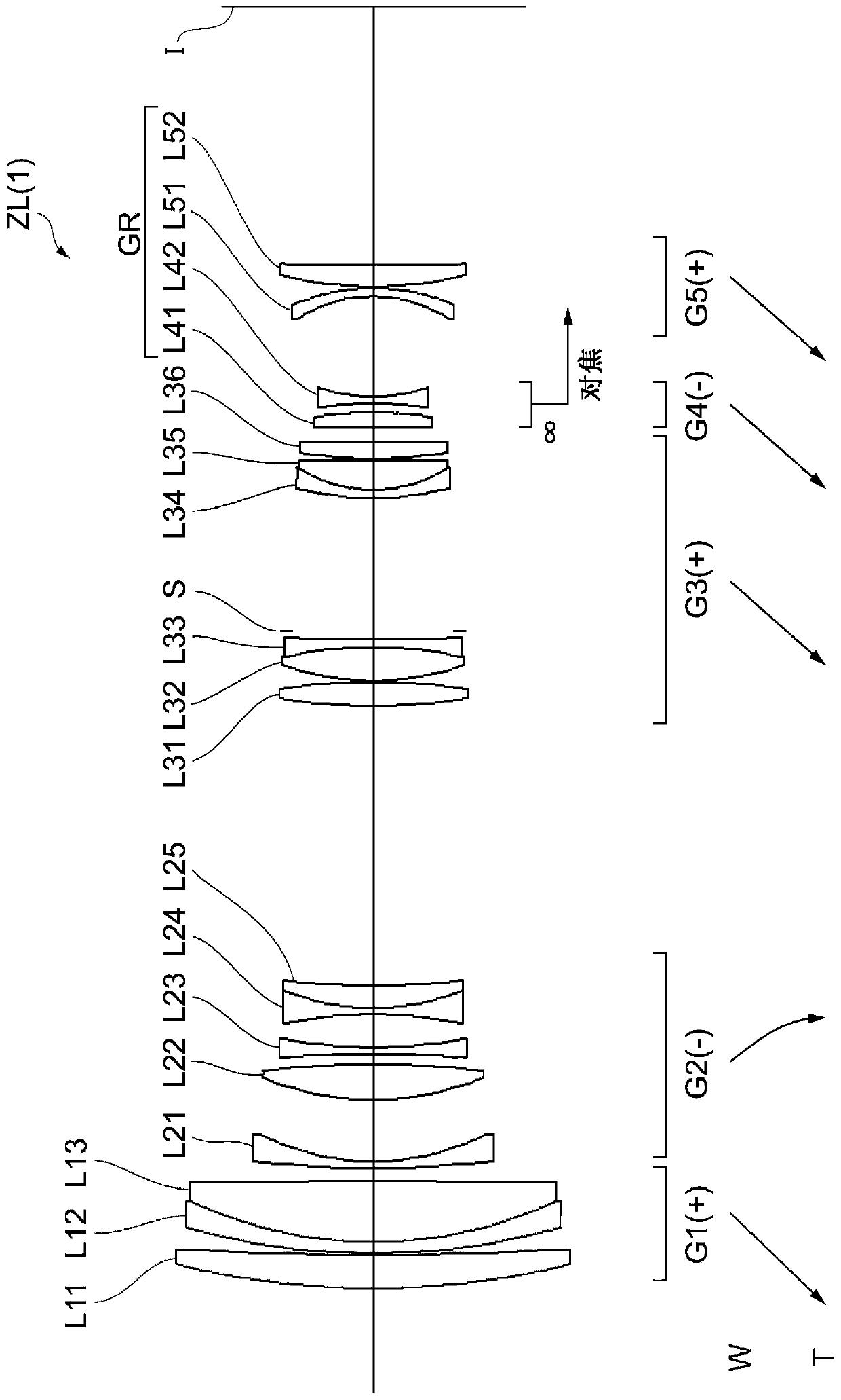
[0100] Hereinafter, a variable power optical system (zoom lens) ZL according to an example of the present embodiment will be described with reference to the drawings. figure 1 , Figure 6 , Figure 11 , Figure 16 , Figure 21 , Figure 26 It is a cross-sectional view showing the structure and power distribution of the variable power optical system ZL{ZL(1)-ZL(6)} of the first to sixth embodiments. In the lower part of the cross-sectional views of the variable power optical systems ZL(1)~ZL(6), the arrows show the lengths of each lens group along the optical axis when zooming from the wide-angle end state (W) to the telephoto end state (T) direction of movement. Furthermore, arrows are used together with the words "focus" to indicate the movement direction of the focus lens group when focusing from infinity to a close object.

[0101] in the above figure 1 , Figure 6 , Figure 11 , Figure 16 , Figure 21 , Figure 26 In , each lens group is represented by a combi...

no. 1 Embodiment

[0111] use Figure 1 to Figure 5 And Table 1 describes the first embodiment. figure 1 It is a figure which shows the lens structure of the variable power optical system of the 1st Example of this embodiment. The variable power optical system ZL(1) of the first embodiment consists of the first lens group G1 with positive refractive power, the second lens group G2 with negative refractive power, and the second lens group G2 with positive optical power arranged in order from the object side. The third lens group G3 having a refractive power, the fourth lens group G4 having a negative refractive power, and the fifth lens group G5 having a positive refractive power are constituted. When zooming from the wide-angle end state (W) to the telephoto end state (T), the first to fifth lens groups G1 to G5 respectively figure 1 to move in the direction indicated by the arrow. In this embodiment, the fourth lens group G4 and the fifth lens group G5 constitute the subsequent lens group GR...

no. 2 Embodiment

[0141] use Figure 6 ~ Figure 10 And Table 2 describes the second embodiment. Figure 6 It is a figure which shows the lens structure of the variable power optical system of the 2nd Example of this embodiment. The variable power optical system ZL(2) of the second embodiment consists of the first lens group G1 with positive refractive power, the second lens group G2 with negative refractive power, and the second lens group G2 with positive optical power arranged in order from the object side. The third lens group G3 having a power, the fourth lens group G4 having a negative power, and the fifth lens group G5 having a negative power constitute a configuration. When zooming from the wide-angle end state (W) to the telephoto end state (T), the first to fifth lens groups G1 to G5 respectively Figure 6 to move in the direction of the arrow. In this embodiment, the fourth lens group G4 and the fifth lens group G5 constitute the subsequent lens group GR.

[0142] The first lens g...


PUM


Abstract

This variable magnification optical system ZL comprises, arranged in order from the object side, a first lens group (G1) having positive refractive power, a second lens group (G2) having negative refractive power, a third lens group (G3) having positive refractive power, and a subsequent lens group (GR). When changing magnification, the interval between the first lens group (G1) and the second lens group (G2) changes, the interval between the second lens group (G2) and the third lens group (G3) changes, and the interval between the third lens group (G3) and the subsequent lens group (GR) changes, and the subsequent lens group (GR) has a focusing lens group that moves during focusing, and satisfies the following conditional expressions: 0.18<(-fF) / f1<0.30, 0.84 <(-f2) / f3<1.20, wherein fF: the focal length of focusing lens subgroup f1: the focal length of the first lens group (G1), f2: the focal length of the second lens group (G2), f3: the focal length of the third lens group (G3)

Description

technical field [0001] The present invention relates to a variable magnification optical system, an optical device and an imaging device using the variable magnification optical system, and a manufacturing method of the variable magnification optical system. Background technique [0002] Conventionally, variable power optical systems suitable for photographic cameras, electronic still cameras, video cameras, and the like have been disclosed (for example, refer to Patent Document 1). However, the conventional zoom optical system has insufficient optical performance. [0003] prior art literature [0004] patent documents [0005] Patent Document 1: Japanese Patent Application Laid-Open No. 4-293007 Contents of the invention [0006] The variable power optical system of the first mode includes a first lens group having positive refractive power, a second lens group having negative refractive power, and a third lens group having positive refractive power arranged in order ...

Claims


Application Information

Patent Timeline
IPC IPC(8): G02B15/20
CPCG02B15/144105G02B15/145105G02B15/145121G02B27/646G03B5/02G03B5/04G03B2205/0015G03B2205/0046
Inventor 町田幸介
Owner NIKON CORP
Features
  • R&D
  • Intellectual Property
  • Life Sciences
  • Materials
  • Tech Scout
  • Unparalleled Data Quality
  • Higher Quality Content
  • 60% Fewer Hallucinations
Learn More