
Automatic quality evaluation for sequence of movement commands

A technology of moving instructions and sequences, applied in program control, instrument, computer control, etc., can solve the problem of not being able to see the surface defects of the workpiece

Active Publication Date: 2019-06-28
SIEMENS AG
View PDF3 Cites 0 Cited by
  • Summary
  • Abstract
  • Description
  • Claims
  • Application Information

AI Technical Summary

Problems solved by technology

Most importantly, however, it is often not possible to see at which specific individual machining process of the workpiece caused the corresponding surface defect

Method used


Image

  • Automatic quality evaluation for sequence of movement commands
  • Automatic quality evaluation for sequence of movement commands
  • Automatic quality evaluation for sequence of movement commands

Examples


Embodiment Construction

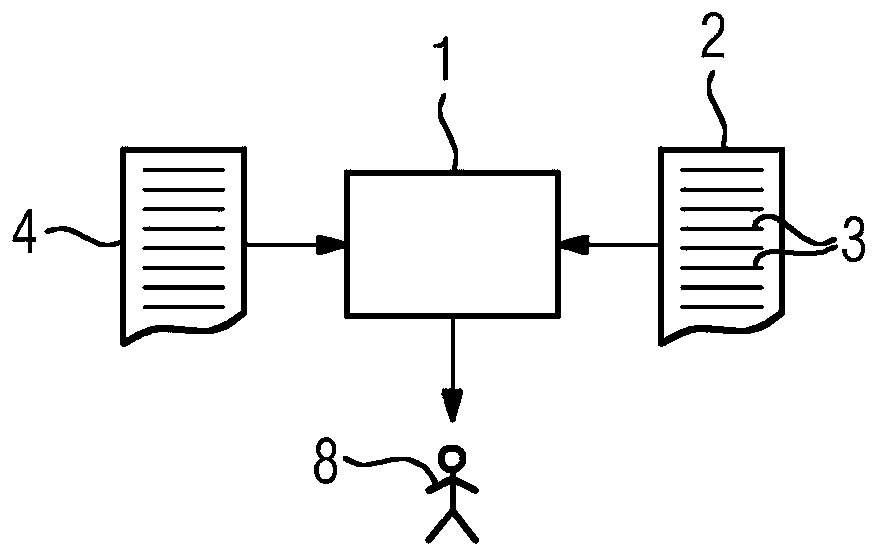
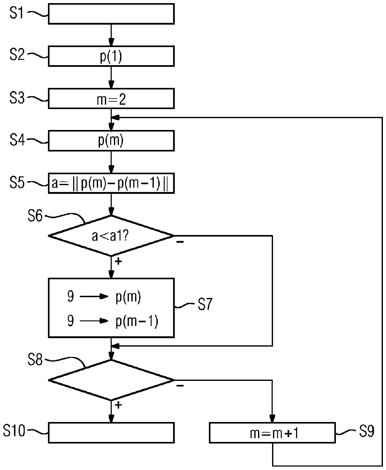
[0069] according to figure 1 , the computing device 1 is programmed with a computer program 2 . The computer program 2 comprises machine code 3 which can be processed by the computing device 1 . The processing of the machine code 3 by the computing device 1 causes the computing device 1 to execute an evaluation method which will be combined below figure 2 and additional figures explain in more detail.

[0070] according to figure 2 , inform the computing device 1 of the movement instruction sequence in step S1. For example, in step S1, the computing device 1 may be notified of the subroutine 4 comprising the sequence (see figure 1 ).

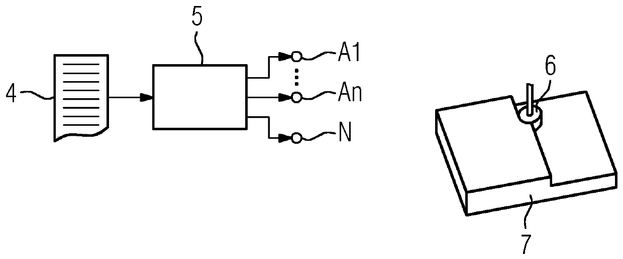
[0071] according to image 3 The subroutine 4 and thus the sequence of movement commands can also be fed to a control device 5 (for example a digital control unit), which can execute the subroutine 4 and thus also the sequence of movement commands. The control device 5 may be identical to the computing device 1 . The control device 5 a...


PUM


Abstract

Movement commands in a sequence of movement commands each define a position (p) to be adopted by a tool (6) of a processing machine relative to a workpiece (7). During the execution of the sequence ofmovement commands by a control device (5) of the processing machine, the tool (6) machines the workpiece (7) at least intermittently. The movement commands, during their execution by the control device (5) of the processing machine, are converted into a trajectory including the defined positions (p). A depiction of the trajectory defined by the sequence of movement commands is output to a user (8). The distances (a) between the positions (p) of directly successive movement commands are ascertained. Positions (p) of directly successive movement commands whose distance (a) is below a predetermined minimum distance (a1) are highlighted in the depiction by means of a marker (9).

Description

technical field [0001] The present invention is based on an evaluation method of a movement instruction sequence, [0002] - where the movement instructions respectively define the position relative to the workpiece to be occupied by the tool of the processing machine, [0003] - wherein the tool handles the workpiece at least sometimes when the sequence of movement instructions is executed by the control device of the processing machine, [0004] - wherein the movement commands are converted into trajectory curves containing defined positions when they are executed by the control device of the processing machine, [0005] - wherein the display of the trajectory curve defined by the sequence of movement instructions is output to the user. [0006] In the context of the present invention, "position" refers only to the translational positioning of the tool relative to the workpiece. Whenever reference is made to the orientation of the tool relative to the workpiece, the corre...

Claims


Application Information

Patent Timeline
Patent Type & Authority Applications(China)
IPC IPC(8): G05B19/4097G05B19/41
CPCG05B19/4068G05B2219/35304G05B2219/35342G05B2219/49084G05B19/4063G05B2219/35349
Inventor 蒂洛·施托尔珀
Owner SIEMENS AG
Learn More