Chair and lifting mechanism therefor

A lifting mechanism and chair technology, applied to chairs, applications, household appliances, etc., can solve the problems that affect the appearance, the waist or headrest cannot reach the lifting height, etc.

Inactive Publication Date: 2019-07-02
UE FURNITURE CO LTD
View PDF0 Cites 1 Cited by
  • Summary
  • Abstract
  • Description
  • Claims
  • Application Information

AI Technical Summary

Problems solved by technology

However, in a certain space, this design has defects, and the lumbar support or headrest cannot reach the required lifting height; if the lifting height of the headrest or lumbar support is to be long enough, then the length or height of the support needs to be increased. But this will affect the appearance, which is not conducive to the design of the chair in the direction of aesthetic appearance

Method used


Image

  • Chair and lifting mechanism therefor
  • Chair and lifting mechanism therefor
  • Chair and lifting mechanism therefor

Examples


Embodiment 1

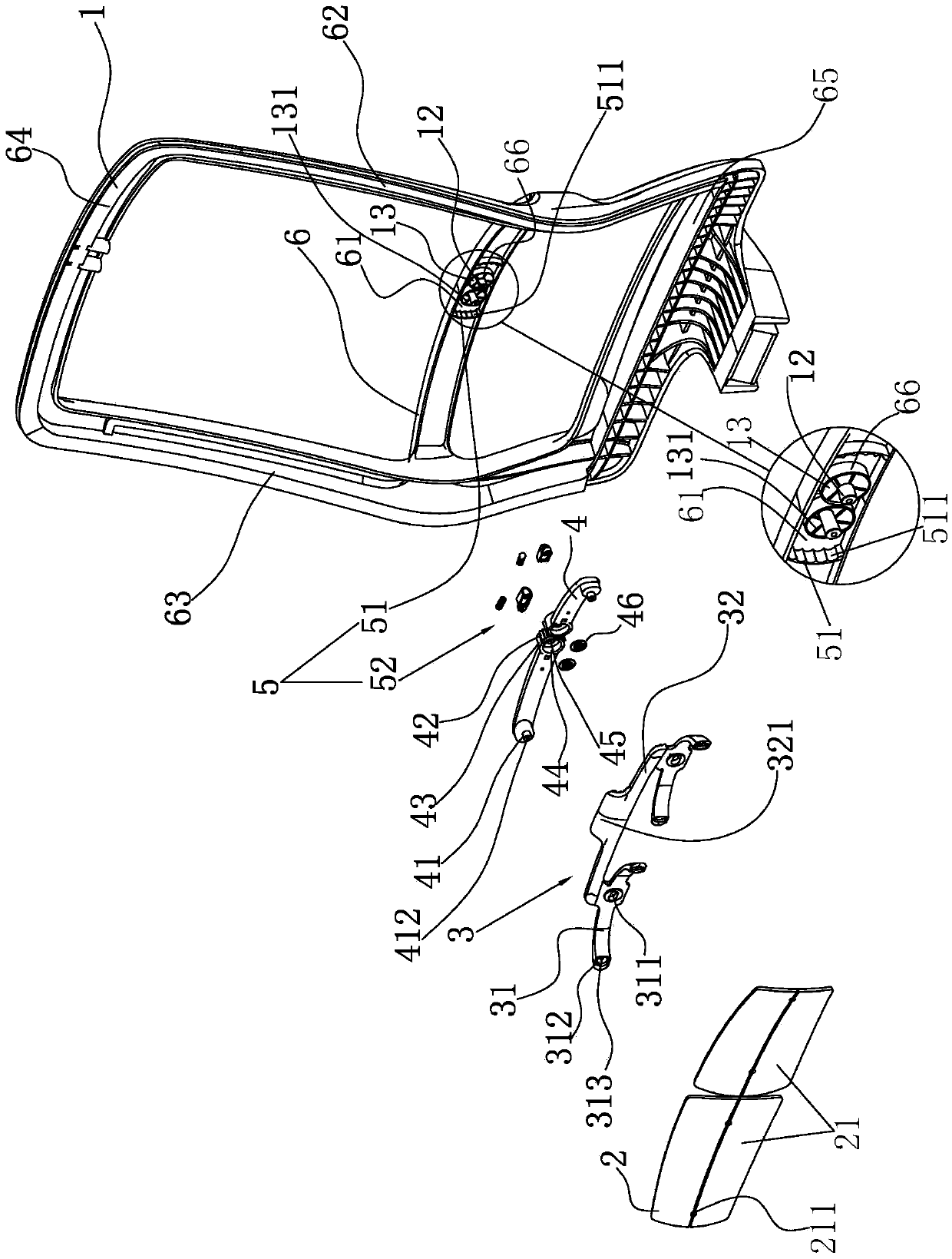
[0053] Such as Figure 1 to Figure 13 A lifting device and a chair back provided with the lifting device are illustrated. The lifting mechanism of the present invention is the core component of the lifting device.

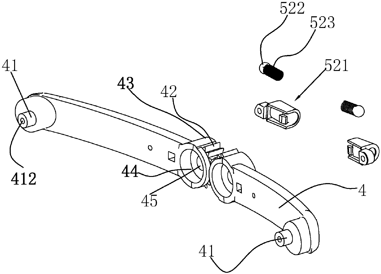
[0054] In this embodiment, the lifting device includes a mounting bracket 3 for configuring the lumbar support 2, two connecting rods 4 for connecting the backrest and the mounting bracket 3, and a locking mechanism for stopping the connecting rods 4 at a predetermined position. Mechanism 5; one end of each of the two connecting rods 4 is rotatably connected to the backrest, and the two connecting rods 4 and the end of the rotatably connected backrest are engaged with each other, and the other end of the connecting rod 4 is movably connected to the mounting bracket 3; During the synchronous rotation of the connecting rods 4 around their respective rotation points, the mounting bracket 3 is raised or lowered.

[0055] In this example, if figure 1 As shown, the ba...

Embodiment 2

[0067] Embodiment 2: the difference between this embodiment and embodiment 1 is: as Figure 14 As shown, the backrest includes a backrest frame 1, and the backrest frame 1 includes a first frame side 62, a second frame side 63, and a top frame connected to the upper and lower ends of the first and second frame sides 62, 63 at intervals from left to right. Side 64, the bottom frame side (not shown), one end of the two connecting rods 4 is directly or indirectly connected to the top frame side 64 in rotation, specifically, one end of the connecting rod 4 is connected to the back of the top frame side 64, and the A headrest 71 is arranged on the bracket 3 .


PUM


Abstract

The invention relates to a chair and a lifting mechanism therefor. The lifting mechanism is arranged on a backrest of the chair and comprises a mounting bracket and two links, wherein the mounting bracket is used for mounting a headrest or lumbar support, and the two links are used for connecting the backrest and the two links; one end of each link is rotatably connected with the backrest, the ends rotatably connected with the backrest of the two links are engaged with each other, and the other end of each link is movably connected with the mounting bracket; the mounting bracket rises or fallsduring synchronous rotation of the two links around respective rotational points. The two links are connected with the backrest, the corresponding ends of the two links are engaged with each other ina gear engaged manner, the two links synchronously rotate around rotational joints with the backrest, and then, the mounting bracket is driven to move up and down; the links are rotatably connected with the backrest, sizes of engaged positions of joints between the links and the backrest are limited, and corresponding positions of the backrest do not need to arrange relatively high supporting bodies in combination with a stroke of the headrest or lumbar support like that in the past.

Description

technical field [0001] The invention belongs to the technical field of office chairs or seats, in particular to a lifting mechanism for office chairs or seats. Background technique [0002] With the improvement of living conditions, people have higher and higher requirements for the comfort of office chairs. As an important part of an office chair, the lumbar support and headrest have an important impact on the comfort of the human body. The traditional lumbar support or headrest is fixed at the corresponding position of the office chair for the human body to rest against the waist or the head. But the lumbar support of fixed position and headrest can't adapt to the people of different heights and shapes to use. [0003] At present, the conventional practice in the market is to set a vertical support on the back of the office chair, a linear or arc-shaped chute on the support, and the waist or headrest is inserted into the chute and slides with the chute. Cooperate. In t...

Claims


Application Information

Patent Timeline
Patent Type & Authority Applications(China)
IPC IPC(8): A47C7/38A47C7/40
CPCA47C7/38A47C7/402
Inventor 郑捷李刚
Owner UE FURNITURE CO LTD
Why Eureka
Try Eureka