Automobile wheel casing part trimming die

A technology for trimming molds and parts, which is applied in the field of trimming molds for automobile wheel cover parts, which can solve the problems of operator safety hazards, easy damage of concealed punches, and inaccurate guidance, so as to improve product qualification rate, stabilize product quality, The effect of solving security risks

Pending Publication Date: 2019-07-02
SHANGHAI ZHONGDA AUTO PARTS
View PDF1 Cites 0 Cited by
  • Summary
  • Abstract
  • Description
  • Claims
  • Application Information

AI Technical Summary

Problems solved by technology

[0002] At present, there are many mold pressing plates for wheel cover parts that only use guide plates for guidance. The distance between the guide plate and the contact surface is relatively long, and the guidance is not accurate, which leads to easy damage to the hidden punch, and even the punch is crushed and ejected from the mold. great safety hazard
[0003] Chinese patent CN 103182425A discloses a trimming and shaping mold for automotive wheel cover parts, including an upper mold, a lower mold, a first trimming knife block, a second trimming knife block, a first shaping mechanism and a second shaping mechanism, and the upper mold Including the upper die base, upper die presser and upper ejector pin, the upper die presser is located below the upper die base, the upper ejector pin is located on the upper die base; the lower die includes the lower die base, lower die core and ejector mechanism, the lower die The core is located above the lower mold base, and the ejector mechanism is located on the lower mold base; the first trimming knife block is located on the left side of the upper mold presser, the second trimming knife block is located on the right side of the upper mold presser, and the first trimming mechanism It is located on the left side of the lower mold core, and the second shaping mechanism is located on the right side of the lower mold core. Although this mold solves the problem of high cost and high failure rate, it still does not solve the potential safety hazards of punch damage and punch ejection.

Method used


Image

  • Automobile wheel casing part trimming die
  • Automobile wheel casing part trimming die

Examples


Embodiment

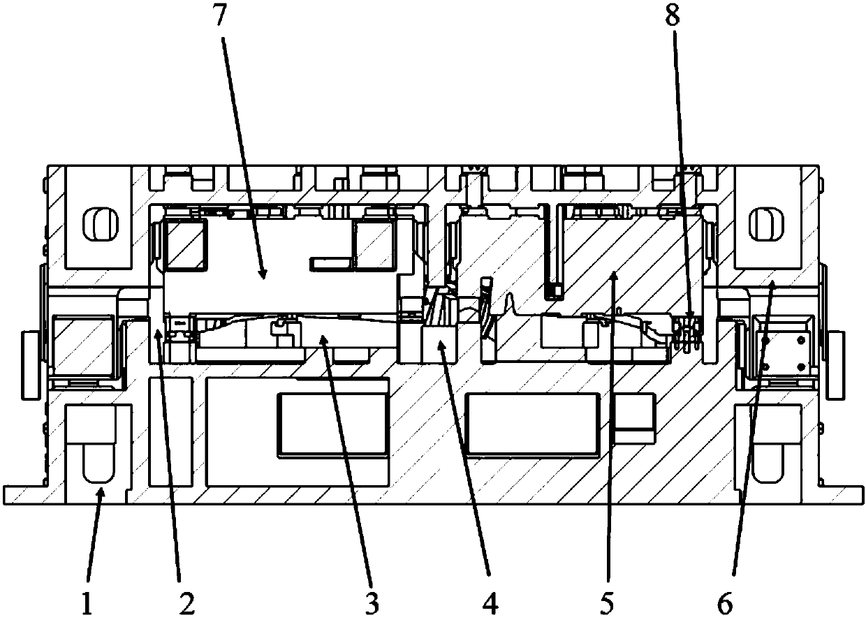
[0023] A kind of trimming mold of automobile wheel cover parts, its structure is as follows figure 1 As shown, it includes an upper mold and a lower mold. The upper mold includes an upper mold base 6, an upper mold presser 5, an upper mold insert 2 and an upper die trimming knife block 4, and an upper mold presser 5 is located below the upper die base 6. The upper die insert 2 and the upper die trimming cutter block 4 are located on the upper die base 6, and the upper die trimming cutter block 4 is arranged on the outer periphery of the workpiece to realize full-circle trimming. The lower mold includes a lower mold base 1, a lower mold core 3 and an ejector mechanism, the lower mold core 3 is positioned above the lower mold base 1, and the ejector mechanism is positioned on the lower mold base 1. In addition, it also includes a conical positioning block 8, which is sleeved on the guide plate provided on the lower mold base 1, and is a conical structure, the bottom of which is ...


PUM

PropertyMeasurementUnit
angleaaaaaaaaaa

Abstract

The invention relates to an automobile wheel casing part trimming die. The automobile wheel casing part trimming die comprises an upper die and a lower die. The upper die comprises an upper die holder, an upper die pressing device, an upper die insert and an upper edge cutting cutter block. The upper die pressing device is located on the lower side of the upper die holder. The upper die insert andthe upper die edge cutting cutter block are located on the upper die holder. The lower die comprises a lower die holder, a lower die core and an ejector mechanism. The lower die core is located on the upper side of the lower die holder. The ejector mechanism is located on the lower die holder. The automobile wheel casing part trimming die further comprises a conical locating block. The conical locking block is arranged on a guide plate arranged on the lower die holder in a sleeving manner. Compared with the prior art, the automobile wheel casing part trimming die has the advantages of being low in production cost, convenient to maintain, safe, reliable and the like.

Description

technical field [0001] The invention relates to a mold, in particular to a trimming mold for automobile wheel cover parts. Background technique [0002] At present, there are many mold pressing plates for wheel cover parts that only use guide plates for guidance. The distance between the guide plate and the contact surface is relatively long, and the guidance is not accurate, which leads to easy damage to the hidden punch, and even the punch is crushed and ejected from the mold. a great safety hazard. [0003] Chinese patent CN 103182425A discloses a trimming and shaping mold for automotive wheel cover parts, including an upper mold, a lower mold, a first trimming knife block, a second trimming knife block, a first shaping mechanism and a second shaping mechanism, and the upper mold Including the upper die base, upper die presser and upper ejector pin, the upper die presser is located below the upper die base, the upper ejector pin is located on the upper die base; the lowe...

Claims


Application Information

Patent Timeline
Patent Type & Authority Applications(China)
IPC IPC(8): B21D28/14B21D28/04
CPCB21D28/04B21D28/14
Inventor 丛培民
Owner SHANGHAI ZHONGDA AUTO PARTS
Why Eureka
Try Eureka