
Material flow diverting device for plastic molds

A technology of plastic molds and shunt devices, applied in the field of plastic molds, can solve problems such as waste, gas outflow, human hazards, etc., and achieve the effect of reducing waste

Active Publication Date: 2019-07-05
山东浩民新材料科技有限公司
View PDF2 Cites 0 Cited by
  • Summary
  • Abstract
  • Description
  • Claims
  • Application Information

AI Technical Summary

Problems solved by technology

[0003] 1. After injecting the heated and melted plastic into the plastic mold through the diverter device, it is necessary to manually close the plastic output end. However, the plastic inlet port is still connected, and the plastic will still flow into the diverter device. When the plastic supply equipment is disconnected from the When the plastic access end is connected, the plastic shunt device that removes the restriction at one end will flow out through the plastic access end, resulting in waste
[0004] 2. At the same time, during the flow process of the heat-melted plastic in the flow distribution device, since the flow distribution device will continue to heat the plastic to prevent it from solidifying, the liquid plastic will undergo thermal decomposition in a small amount and produce a small amount of gas when it is subjected to high temperature again. The gas has strong toxicity. When the injection molding is finished, the gas will easily flow out through the plastic access port, causing harm to the human body.

Method used


Image

  • Material flow diverting device for plastic molds
  • Material flow diverting device for plastic molds
  • Material flow diverting device for plastic molds

Examples


Embodiment Construction

[0026] In order to make the technical means, creative features, goals and effects achieved by the present invention easy to understand, the present invention will be further described below in conjunction with specific embodiments.

[0027] Such as Figure 1-Figure 5 As shown, the present invention provides a technical scheme of a material splitting device for plastic molds:

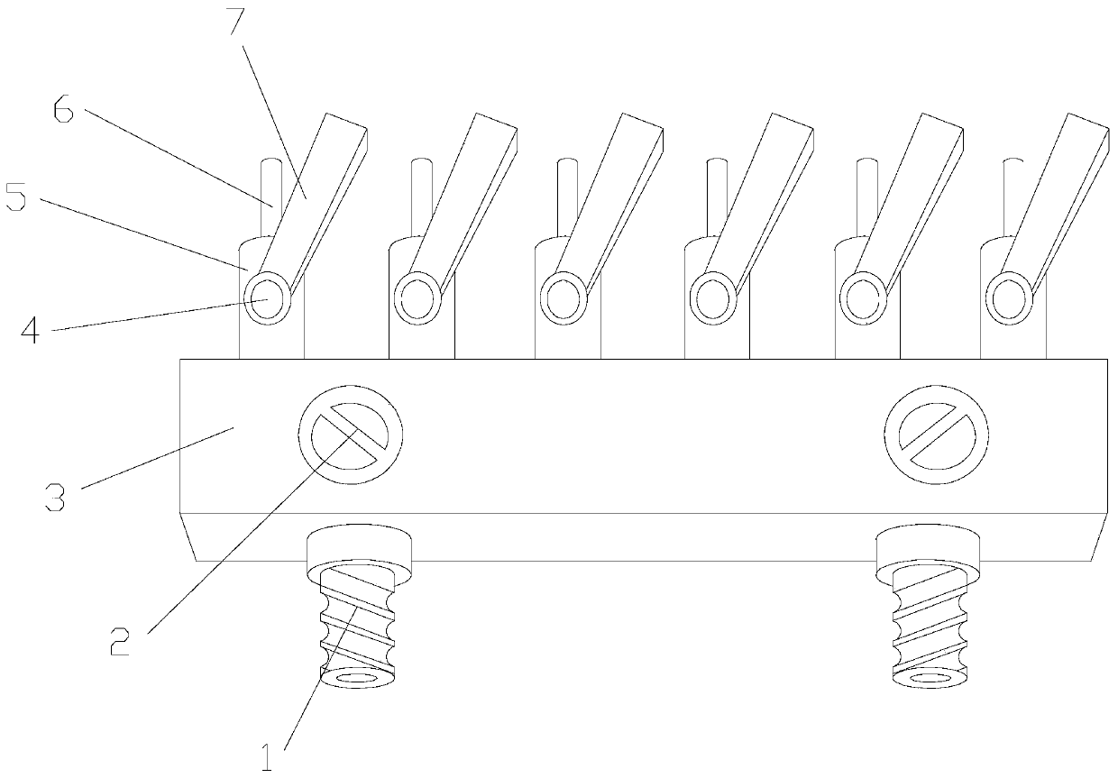
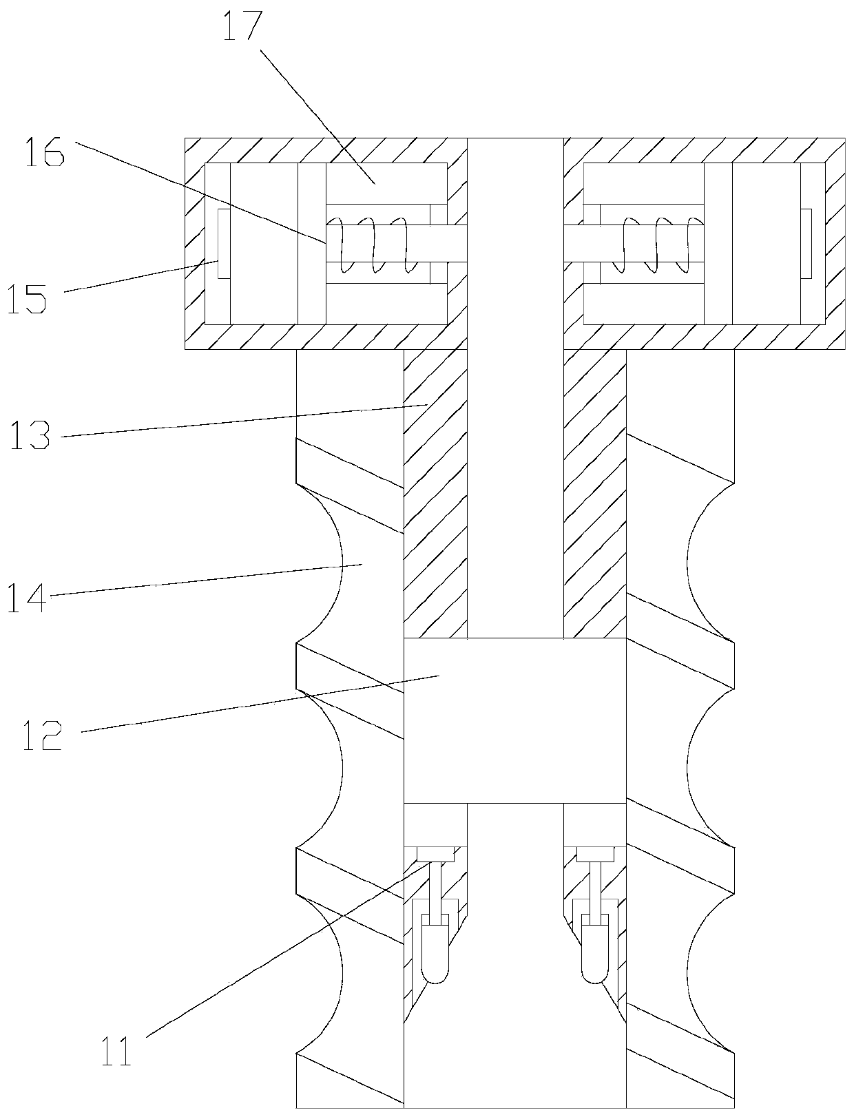
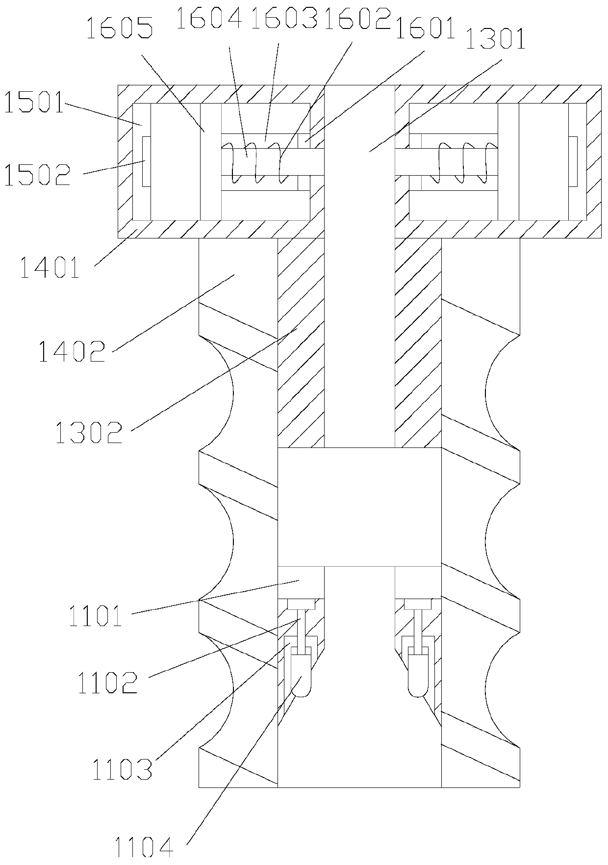
[0028] A material diversion device for plastic molds, the structure of which includes a self-sealing material inlet device 1, a constant temperature heating end 2, a material diversion device body 3, a connecting rotary valve 4, a connecting pipe 5, a material injection pipe 6, and an action handle 7, The self-enclosed material inlet device 1 is arranged at the lower end of the material distribution device body 3 and is connected by embedded installation, and the constant temperature heating end 2 is arranged inside the material distribution device body 3 and is connected by a fixed installation method, ...


PUM


Abstract

The invention discloses a material flow diverting device for plastic molds. The material flow diverting device structurally comprises self-sealing material entering devices, constant-temperature heating ends, a material flow diverting mounting standby body, linkage rotary valves, linkage pipelines, material injection pipes and acting rotary handles. The self-sealing material entering devices are arranged at the lower end of the material flow diverting mounting standby body and connected with the material flow diverting mounting standby body in an embedded mounting manner. The constant-temperature heating ends are arranged in the material flow diverting mounting standby body and connected with the material flow diverting mounting standby body in a fixed mounting manner. A structure for automatically sealing plastic switching-in ends at the moment when injection molding work stops is arranged, waste of plastic can be reduced, meanwhile, a structure capable of collecting and treating gasin the pipelines after the material flow diverting mounting standby body stops operating is arranged inside, and therefore the situation that the harmful gas runs outside, so that the human body is harmed is effectively avoided.

Description

technical field [0001] The invention relates to the field of plastic molds, more precisely, it relates to a material diverting device for plastic molds. Background technique [0002] During the working process of the plastic mold, it is necessary to inject the heated and melted plastic into the plastic mold, and divide the plastic through the diversion device. The diversion device has the characteristics of constant temperature and strong sealing. But, there is following shortcoming in this shunt device at present: [0003] 1. After injecting the heated and melted plastic into the plastic mold through the diverter device, it is necessary to manually close the plastic output end. However, the plastic inlet port is still connected, and the plastic will still flow into the diverter device. When the plastic supply equipment is disconnected from the When the plastic access end is connected, the plastic shunt device that removes the restriction at one end will flow out through th...

Claims


Application Information

Patent Timeline
IPC IPC(8): B29C45/18
CPCB29C45/18
Inventor 孙加亮曾清民练陈敏
Owner 山东浩民新材料科技有限公司
Learn More