Anti-collision device for highway bridge

A road bridge, anti-collision technology, applied in road safety devices, bridges, bridge construction, etc., can solve the problems of poor interception performance, cars rushing out of roads and bridges, guardrails and cars are prone to damage, and reduce fragmentation Probability, lifespan increase effect

Active Publication Date: 2019-07-05
河南中部建设工程有限公司
View PDF5 Cites 12 Cited by
  • Summary
  • Abstract
  • Description
  • Claims
  • Application Information

AI Technical Summary

Problems solved by technology

Usually, the guardrails on both sides of the road or bridge are directly fixed. When the car accidentally collides with the guardrail, both the guardrail and the car are prone to damage, and the fixed guardrail has poor interception performance against the high-speed impact of the car. Car crashes off road and bridge

Method used


Image

  • Anti-collision device for highway bridge
  • Anti-collision device for highway bridge
  • Anti-collision device for highway bridge

Examples


no. 1 approach

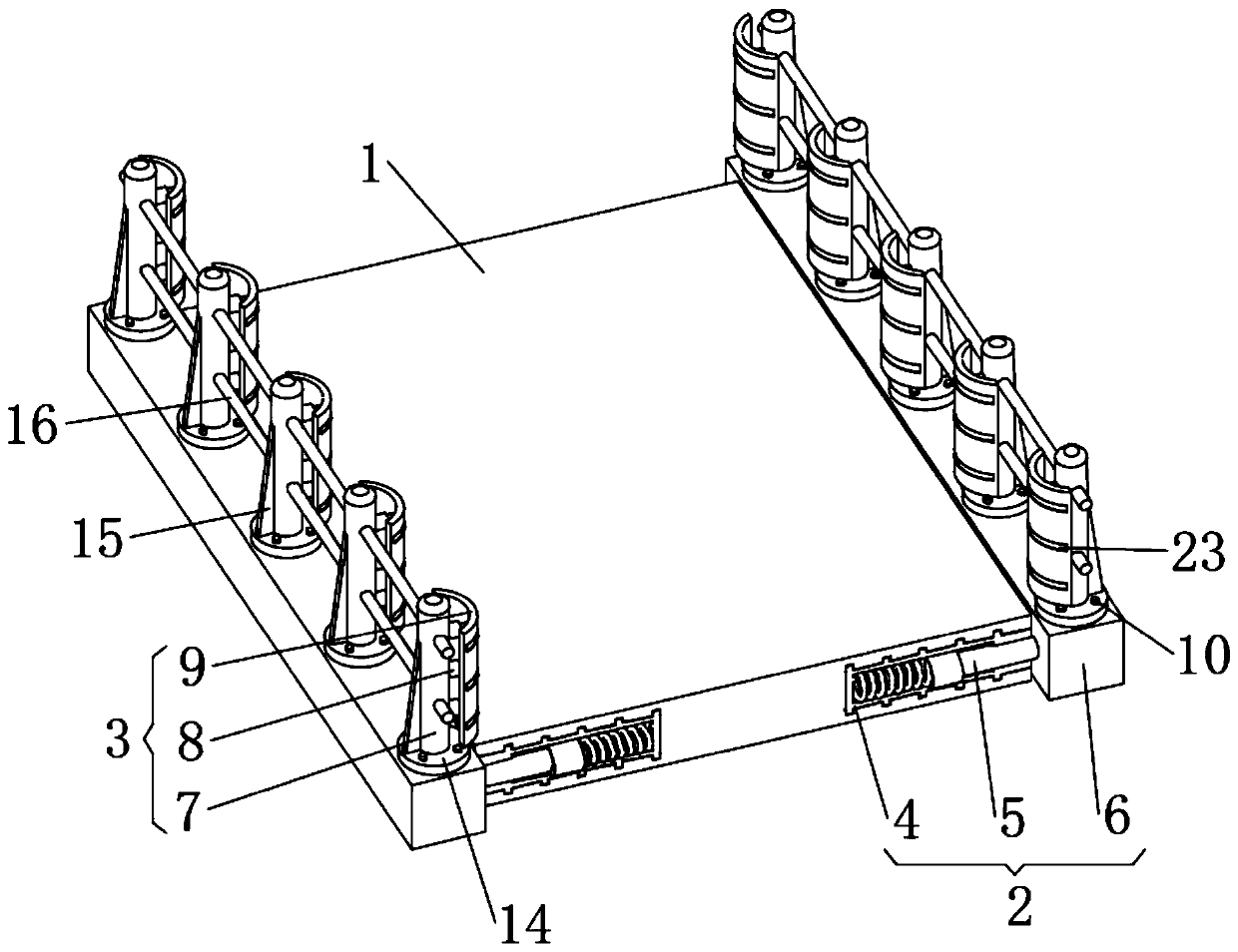
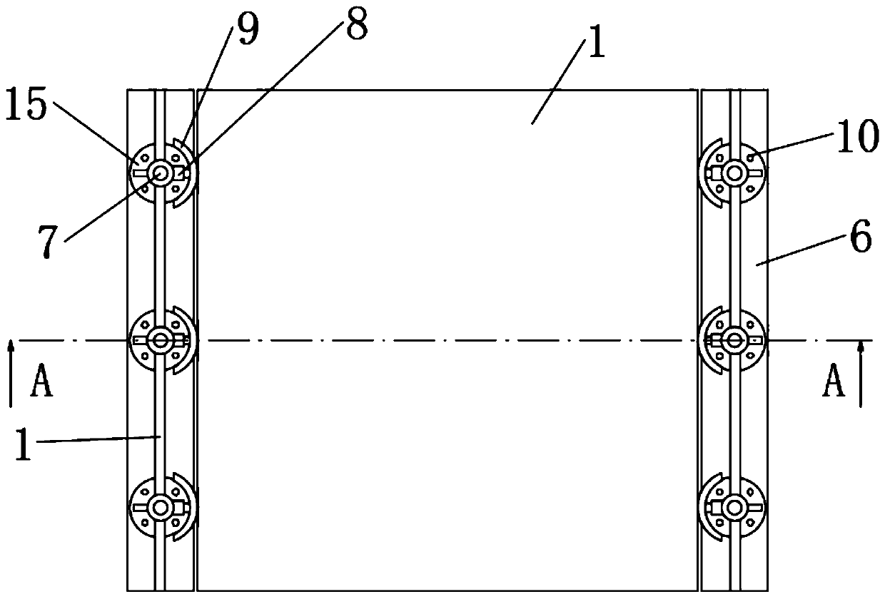
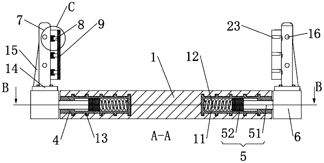
[0022] First embodiment: the present invention provides such as Figure 1-5 The shown a kind of anti-collision device for highway bridge, a kind of anti-collision device for highway bridge, comprises road panel 1, main buffer mechanism 2 and auxiliary buffer mechanism 3, and the two sides of road panel 1 are provided with multiple groups of symmetrical settings The main buffer mechanism 2, the main buffer mechanism 2 is composed of the main buffer sleeve 4, the main buffer shaft 5 and the guardrail support bar 6, combined with figure 1 and image 3 As shown, the main buffer sleeve 4 is embedded in both sides of the road panel 1, and the outer wall of the main buffer sleeve 4 is integrally formed with a plurality of ring-shaped snap rings 13, and the plurality of snap rings 13 are evenly arranged on the main buffer On the outer wall of the sleeve 4, the snap ring 13 is snapped into the inside of the road panel 1, and the snap ring 13 is bonded to the inside of the road panel 1...

no. 2 approach

[0028] The second embodiment: an anti-collision device for a road bridge, comprising a road panel 1, a main buffer mechanism 2 and a secondary buffer mechanism 3, the two sides of the road panel 1 are provided with multiple sets of symmetrically arranged main buffer mechanisms 2, The main buffer mechanism 2 includes a main buffer sleeve 4, a main buffer shaft 5 and a guardrail support strip 6. The main buffer sleeve 4 is embedded in both sides of the road surface 1, and the outer wall of the main buffer sleeve 4 is integrated. A plurality of ring-shaped snap rings 13 are formed, and the inside of the main buffer sleeve 4 is provided with a pull shaft sliding cavity 11, and the opening of the pull shaft sliding cavity 11 is arranged on the side wall of the road panel 1, and the inside of the pull shaft sliding cavity 11 A main buffer shaft 5 is provided, and the main buffer shaft 5 includes a pull shaft 51 and a pull shaft chuck 52. The pull shaft chuck 52 is clamped inside the ...


PUM


Abstract

The invention discloses an anti-collision device for a highway bridge, and relates to the field of highway bridge equipment. The anti-collision device includes a road slab, main buffering mechanisms and auxiliary buffering mechanisms, wherein multiple groups of the main buffering mechanisms are symmetrically arranged on the two sides of the road slab, the main buffering mechanisms include main buffering sleeves, main buffering shafts and fence supporting bars, multiple groups of the auxiliary buffering mechanisms are arranged on the upper surfaces of the fence supporting bars in the longitudinal direction, and the auxiliary buffering mechanisms include fence supporting columns, buffering telescopic rods and protective plates. According to the anti-collision device, in protection, the fencesupporting columns inclined outwards by impacting, the fence supporting bars are moved outwards of the road slab under dragging of the fence supporting columns, the main buffering shafts connected with the fence supporting bars are drawn out of pulling shaft sliding cavities formed in the main buffering sleeves, main pulling springs connected between the main buffering shafts and the inner partsof the pulling shaft sliding cavities are stretched, the main pulling springs can effectively buffer the impact force generated in car impacting, and a car can be effectively held up.

Description

technical field [0001] The invention relates to the field of highway bridge facilities, in particular to an anti-collision device for highway bridges. Background technique [0002] Guardrails are usually installed on both sides of the road or bridge to prevent the vehicle from deviating from the road or bridge during driving, especially for cars traveling at high speed on the bridge. Once the guardrail does not stop the car, the car will fall accidentally. Usually, the guardrails on both sides of the road or bridge are directly fixed. When the car accidentally collides with the guardrail, both the guardrail and the car are prone to damage, and the fixed guardrail has poor interception performance against the high-speed impact of the car. Accidents where cars ran off roads and bridges. Therefore, it is necessary to invent a kind of anti-collision device for highway bridge to solve the above problems. Contents of the invention [0003] The object of the present invention i...

Claims


Application Information

Patent Timeline
Patent Type & Authority Applications(China)
IPC IPC(8): E01D19/10E01F15/04
CPCE01D19/103E01F15/0461
Inventor 不公告发明人
Owner 河南中部建设工程有限公司
Why Eureka
Try Eureka