
Illumination device

A technology for a lighting device and an installation shell, which is applied in the field of lighting, can solve problems such as shadows on the light-emitting surface of the lighting device, and achieve the effects of weakening the shadows and uniform light output.

Pending Publication Date: 2019-07-05
OPPLE LIGHTING +1
View PDF0 Cites 0 Cited by
  • Summary
  • Abstract
  • Description
  • Claims
  • Application Information

AI Technical Summary

Problems solved by technology

However, in some lighting devices, non-light source modules need to be installed in the light source cavity. Due to the interference of the non-light source modules on the light source, shadows will be produced on the light-emitting surface of the lighting device.

Method used


Image

  • Illumination device
  • Illumination device
  • Illumination device

Examples


Embodiment Construction

[0043] In order to make the purpose, technical solution and advantages of the present invention clearer, the technical solution of the present invention will be clearly and completely described below in conjunction with specific embodiments of the present invention and corresponding drawings. Apparently, the described embodiments are only some of the embodiments of the present invention, but not all of them. Based on the embodiments of the present invention, all other embodiments obtained by persons of ordinary skill in the art without making creative efforts belong to the protection scope of the present invention.

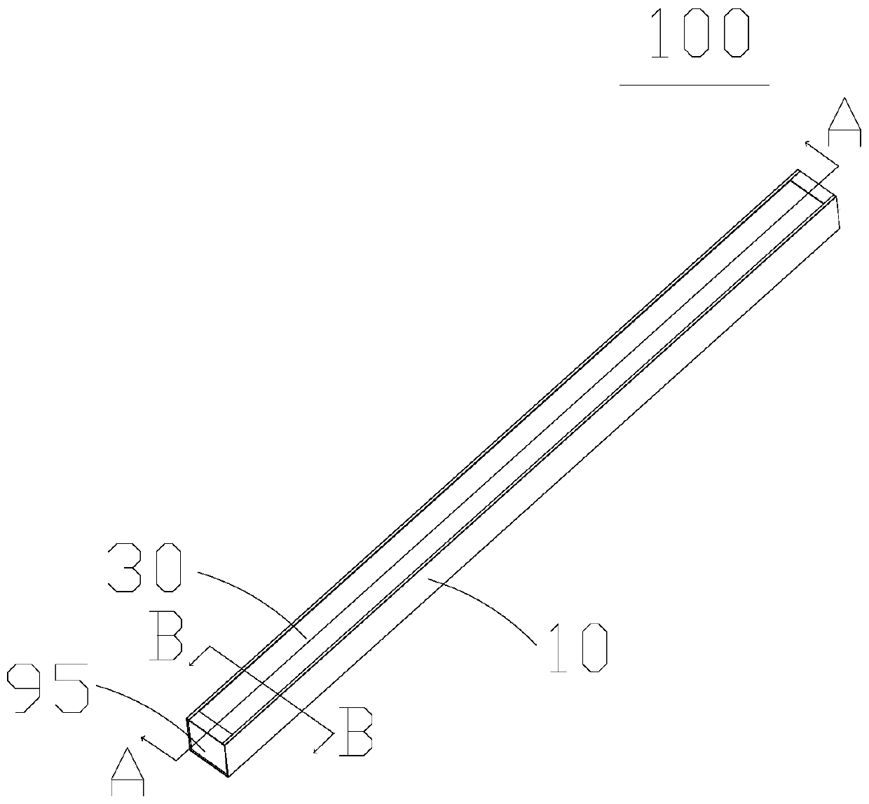
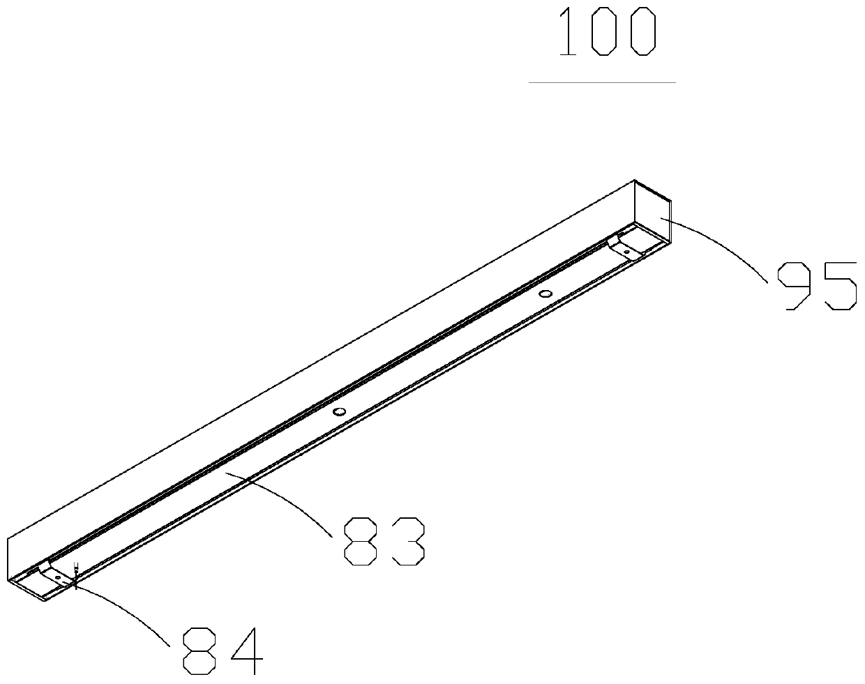
[0044] ginseng Figure 1 to Figure 5, the embodiment of the present invention discloses a lighting device 100 , including a housing 10 , a light source module 20 , a first optical element 30 , a second optical element 40 and a non-light source module 50 . The casing 10 and the first optical element 30 enclose a first light source cavity 61 , and the light source ...


PUM


Abstract

The invention discloses an illumination device and belongs to the technical field of illumination. The illumination device comprises a shell, a light source module, a first optical element, a second optical element and a non-light source module. The shell and the first optical element form a first light source cavity in a surrounding mode. The light source module is arranged in the first light source cavity and comprises a light source plate and a shining unit arranged on the light source plate. The second optical element is arranged in the first light source cavity, and the second optical element and the light source module form a second light source cavity in a surrounding mode. The non-light source module and at least part of the shining unit on the light source plate are held in the second light source cavity.

Description

technical field [0001] The invention relates to the technical field of lighting, in particular to a lighting device. Background technique [0002] The lighting fixture has a light source module installed in the light source cavity, and other non-light source modules that cannot emit light, such as a power supply module or a sensing module. [0003] Typically, non-light source modules are not installed in the light source cavity. However, in some lighting devices, the non-light source modules need to be installed in the light source cavity. Due to the interference effect of the non-light source modules on the light source, shadows will be produced on the light-emitting surface of the lighting device. Contents of the invention [0004] In order to solve the above problems, the present invention provides a lighting device. [0005] The lighting device provided by the present invention includes: a casing, a light source module, a first optical element, a second optical eleme...

Claims


Application Information

Patent Timeline
Patent Type & Authority Applications(China)
IPC IPC(8): F21V19/00F21V17/10F21V17/16F21V13/04F21V23/00
CPCF21V19/0015F21V17/10F21V17/168F21V13/04F21V23/003
Inventor 赵玉新谭兴臣寸加春
Owner OPPLE LIGHTING
Learn More