

Back-to-light system
A backlight system and light source technology, applied in the field of backlight systems, can solve the problems of uneven light output, complex structure and high cost, and achieve the effects of uniform light output, simple structure and reduced cost
- Summary
- Abstract
- Description
- Claims
- Application Information
AI Technical Summary
Problems solved by technology
Method used
Image

Examples
Embodiment Construction
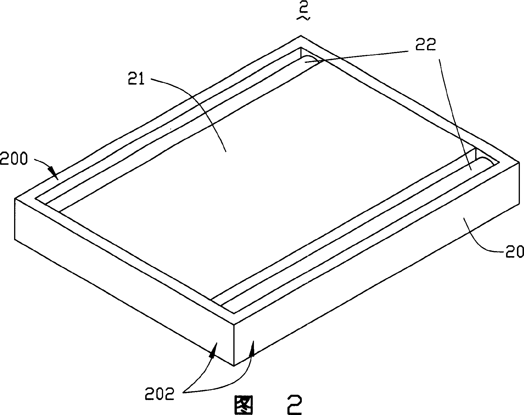
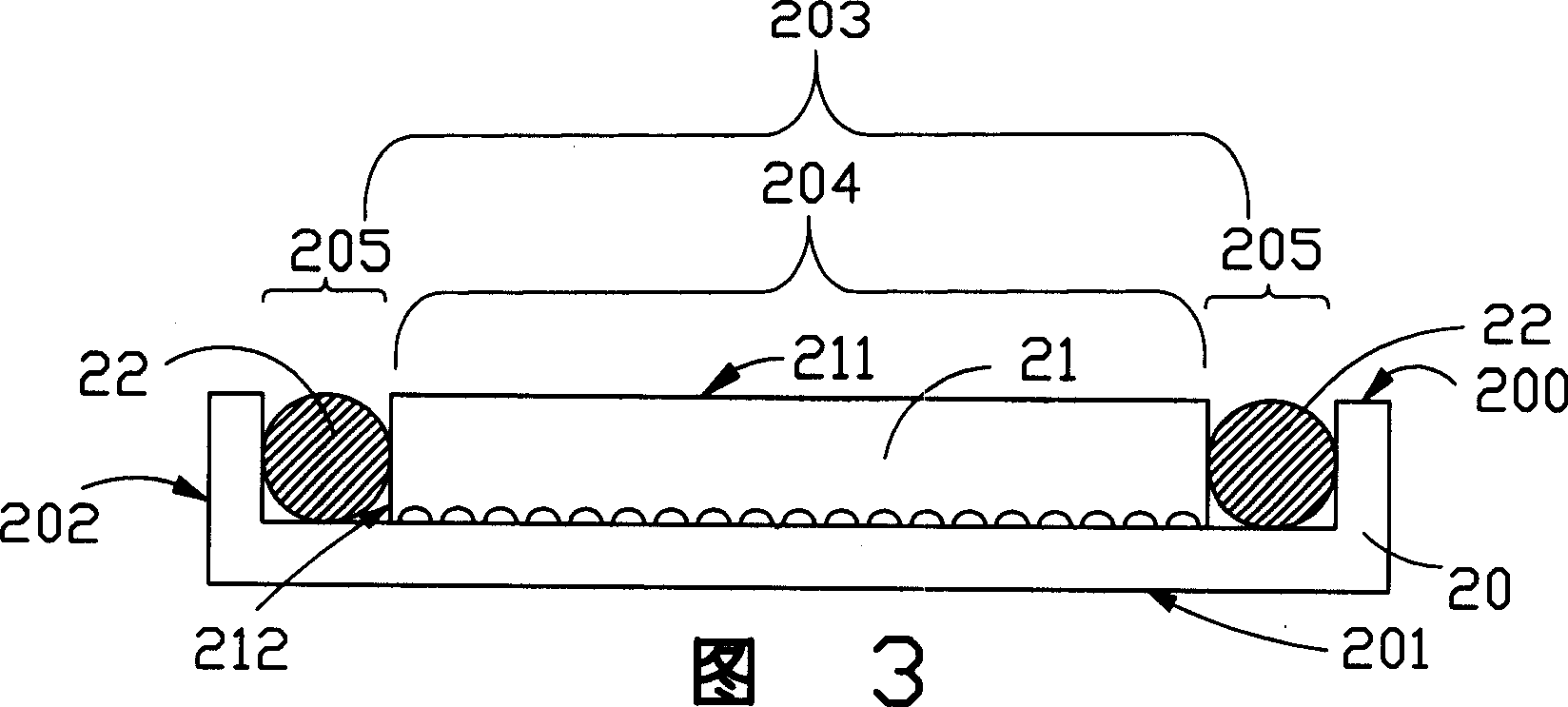
[0015] Please refer to FIG. 2 and FIG. 3 together, which are schematic diagrams of the first embodiment of the backlight system of the present invention. The backlight system 2 includes a frame body 20 , a light guide plate 21 and two light sources 22 . The frame body 20 is in the shape of a box, and its material is a highly reflective PC (Polycarbonate, polycarbonate) material with a reflectivity greater than 95%. The frame body 20 includes an upper surface 200 , a bottom surface 201 and a plurality of side surfaces 202 . In the center of the upper surface 200 of the frame body 20 there is a concave area 203 with an upward opening. Protruding points are provided on the surface, and the second space 205 is disposed on both sides of the first space 204 ; the light guide plate 21 is disposed in the first space 204 of the concave region 203 , and is integrally formed with the frame body 20 . The light guide plate 21 includes a light emitting surface 211 and two light incident su...
PUM
| Property | Measurement | Unit |
|---|---|---|
| reflectance | aaaaa | aaaaa |
Abstract
Description
Claims
Application Information