Backlight module and light source assembly thereof

A technology of light source components and backlight modules, applied in the field of backlight modules, can solve problems such as unfavorable thin design and thick thickness of backlight modules, and achieve the effects of avoiding bright light sources and shortening light mixing distance.

Active Publication Date: 2015-06-10
FUTAIHUA PRECISION ELECTRONICS ZHENGZHOU
View PDF3 Cites 11 Cited by
  • Summary
  • Abstract
  • Description
  • Claims
  • Application Information

AI Technical Summary

Problems solved by technology

However, such a backlight module is relatively thick, which is not conducive to thin design

Method used


Image

  • Backlight module and light source assembly thereof
  • Backlight module and light source assembly thereof
  • Backlight module and light source assembly thereof

Examples


Embodiment Construction

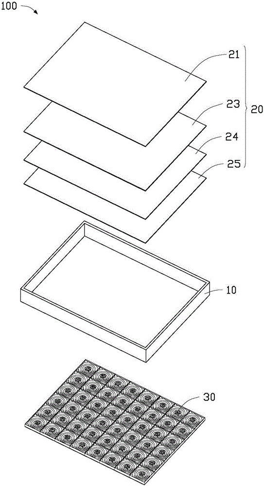
[0016] see figure 1 The backlight module 100 according to the embodiment of the present invention includes a frame body 10 , an optical film set 20 accommodated in the frame body 10 , and a plurality of light source assemblies 30 accommodated in the frame body 10 and located below the optical film set 20 . Multiple light source assemblies 30 are arranged in matrix.

[0017] The frame body 10 is made of metal or plastic with high reflectivity. It can be understood that the frame body 10 can also be made of metal or plastic coated with a high-reflectivity coating.

[0018] The optical film set 20 includes a plurality of optical elements. Preferably, the plurality of optical elements are a diffusion sheet 21 , a prism sheet 23 , a diffusion sheet 24 and a diffusion plate 25 which are stacked.

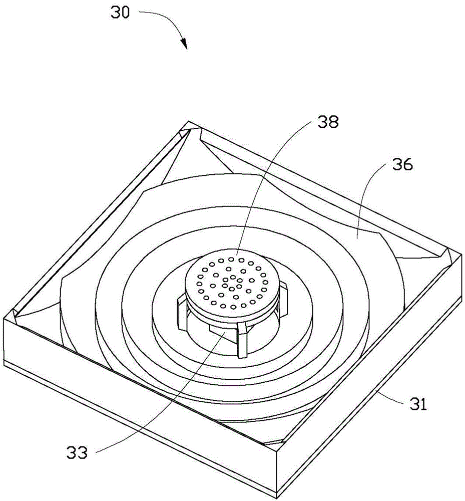
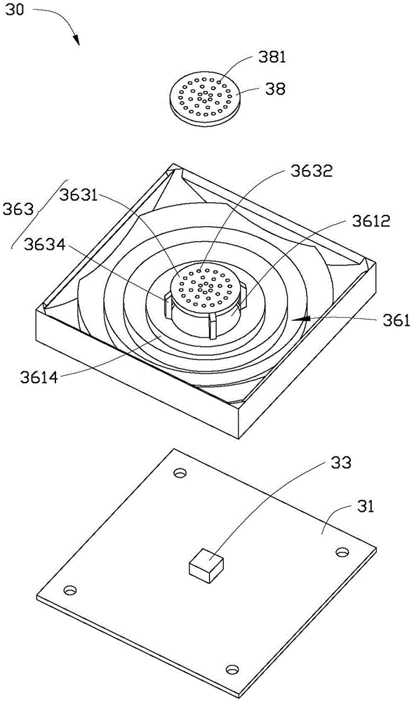
[0019] Please also refer to Figure 2 to Figure 4 . Each light source assembly 30 includes a substrate 31 , an LED light source 33 fixed in the middle of the substrate 31 , a packagin...


PUM


Abstract

A light source assembly includes a base plate, a light source secured on the base plate, a first reflection member, a second reflection member, and a diffusion plate. The first reflection member includes a base portion secured on the base plate and a plurality of protrusions with reflection surfaces inclined to the base plate. A through hole is defined on the base portion to receive the light source. Each protrusion protrudes from a side of the base portion away from the base plate and extends around the through hole. The second reflection member includes a reflection portion defining a plurality of light holes. The diffusion plate covers the second reflection member. Light emitting from the light source transmits to the light guide assembly via the reflection portion and the reflection surfaces.

Description

technical field [0001] The invention relates to a backlight module used in the field of liquid crystal display, in particular to a direct-type backlight module and a light source assembly thereof. Background technique [0002] The liquid crystal display device is a passive display device, which does not have light-emitting characteristics, and needs to be provided with a backlight module to realize the display function. Backlight modules can be divided into edge-type backlight modules and direct-type backlight modules according to their structures. The existing direct type backlight module includes an optical film, a diffusion plate, a light guide plate and a light source. The diffuser plate is arranged above the light source and is separated from the light source by a light mixing distance, and the optical film is arranged above the diffuser plate. In order to make the brightness of the entire backlight uniform, it is necessary to increase the light mixing distance betwee...

Claims


Application Information

Patent Timeline
Patent Type & Authority Applications(China)
IPC IPC(8): F21S8/00F21V13/04F21V17/00G02F1/13357F21Y101/02
CPCF21S8/00F21V7/22F21V13/04F21V17/00F21Y2101/00G02F1/133603G02B5/02G02B19/0023G02B19/0066G02F1/133605G02F1/133606G02B5/0231
Inventor 章绍汉
Owner FUTAIHUA PRECISION ELECTRONICS ZHENGZHOU
Why Eureka
Try Eureka