
LED encapsulating structure and method thereof

A technology of light-emitting diodes and packaging structures, which is applied in the direction of electrical components, electric solid-state devices, circuits, etc., can solve problems such as uneven lighting, reduced luminous brightness, and poor light spots, so as to achieve uniform light output, no decrease in brightness, and increased uniformity Effect

Inactive Publication Date: 2010-11-17
LEDMAN OPTOELECTRONICS
View PDF5 Cites 11 Cited by
  • Summary
  • Abstract
  • Description
  • Claims
  • Application Information

AI Technical Summary

Problems solved by technology

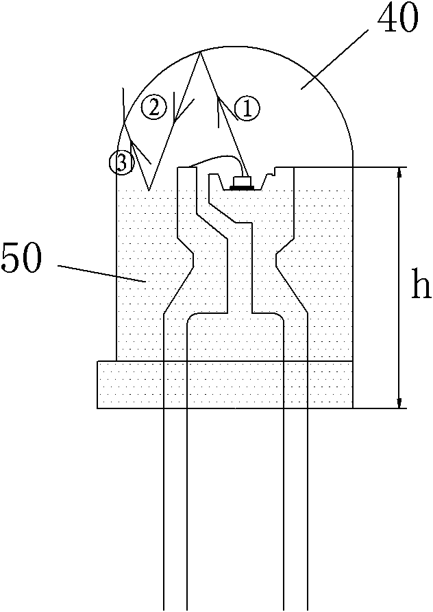
[0004] Because the outer sealant is packaged with transparent glue, this advantage is: the brightness of the light-emitting diode is high; the disadvantage is: uneven light emission, uneven light emission, poor light spots, and poor display effects in practical applications (such as figure 1 shown)
[0005] The common way in the prior art to solve the above-mentioned technical problems is to use an external sealing structure with a diffusing agent. The advantages of this solution are: uniform light emission and better light spots; the disadvantage is that the luminous brightness is reduced

Method used


Image

  • LED encapsulating structure and method thereof
  • LED encapsulating structure and method thereof
  • LED encapsulating structure and method thereof

Examples


Embodiment Construction

[0023] In order to describe the technical content, structural features, achieved goals and effects of the present invention in detail, the following will be described in detail in conjunction with the embodiments and accompanying drawings.

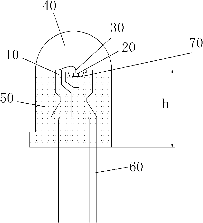
[0024] see figure 2 , embodiments of the light emitting diode packaging structure of the present invention include:

[0025] The bracket 10, the LED chip 20, the wire 30, and the transparent outer sealant 40 connected up and down in layers and the outer sealant 50 added with a diffusing agent;

[0026] The bracket 10 includes two parallel electrodes 60, one end of the electrodes 60 is provided with a groove receiving seat, and the LED chip 20 is fixed on the bottom of the groove receiving seat through a primer 70;

[0027] One end of the wire 30 is connected to the LED chip 20, and the other end is connected to the bracket 10;

[0028] The transparent outer sealant 40 and the outer sealant 50 added with diffusing agent cover the bracket...


PUM


Abstract

The invention discloses an LED encapsulating structure and a method thereof. The encapsulating structure comprises a bracket, an LED wafer, a wire, transparent external encapsulating glue and external encapsulating glue in which a dispersant is added, wherein the transparent external encapsulating glue is in up-and-down hierarchical connection with the external encapsulating glue in which the dispersant is added; the bracket comprises two parallel electrodes; the end surface of one end of the electrodes is provided with a groove supporting seat; the LED wafer is fixed on the bottom of the groove supporting seat by primer; the wire is connected with the LED wafer and the electrodes; the transparent external encapsulating glue is used for coating the LED wafer, the wire and the part of the bracket where the groove supporting seat is located; the transparent external encapsulating glue is higher than the groove supporting seat and is used for coating the LED wafer; the external encapsulating glue in which the dispersant is added is lower than the groove supporting seat, wherein the dispersant is distributed on the external encapsulating glue in which the dispersant is added; and no dispersant is distributed on the transparent external encapsulating glue. By adopting the encapsulating structure, good spot and uniform illumination of the light emitted by an LED are realized without reducing the brightness.

Description

technical field [0001] The invention relates to the technical field of light-emitting diodes (LEDs), in particular to a light-emitting diode packaging structure and a method thereof. Background technique [0002] As a light source, light-emitting diodes have the advantages of long service life, high brightness, and low power consumption, so they can be widely used in lighting lamps, displays, indicator lights, and automobile brake lights. [0003] The light-emitting diodes of the existing transparent models include: the positive and negative electrode brackets have a groove above one pole for accommodating the light-emitting chip, and are connected to the chip with welding wires to form a path; The outside of the bracket is poured with glue through a mold to form a required shape, thereby forming a light-emitting diode that can emit light of various colors. [0004] Because the outer sealant is packaged with transparent glue, this advantage is: the brightness of the light-e...

Claims


Application Information

Patent Timeline
Patent Type & Authority Applications(China)
IPC IPC(8): H01L33/48H01L33/56
CPCH01L2224/48091H01L2224/48247H01L2924/00014
Inventor 李漫铁李志新吴新华谢振胜
Owner LEDMAN OPTOELECTRONICS
Learn More