
Pixel driving circuit and display panel

A pixel driving circuit and circuit technology, applied in the field of display panels and pixel driving circuits, can solve the problems of lowering user experience, poor stability of micro-light emitting diodes, and inability to control the brightness and gray scale of micro-light emitting diodes, etc., to ensure luminous efficiency, Improved stability, accurate and effective control

Active Publication Date: 2019-07-05
BOE TECH GRP CO LTD
View PDF16 Cites 26 Cited by
  • Summary
  • Abstract
  • Description
  • Claims
  • Application Information

AI Technical Summary

Problems solved by technology

[0003] However, in the related art, the brightness and gray scale of micro-light emitting diodes cannot be accurately and e

Method used


Image

  • Pixel driving circuit and display panel
  • Pixel driving circuit and display panel
  • Pixel driving circuit and display panel

Examples


Embodiment Construction

[0029] Embodiments of the present invention are described in detail below, examples of which are shown in the drawings, wherein the same or similar reference numerals designate the same or similar elements or elements having the same or similar functions throughout. The embodiments described below by referring to the figures are exemplary and are intended to explain the present invention and should not be construed as limiting the present invention.

[0030] The pixel driving circuit and the display panel proposed according to the embodiments of the present invention are described below with reference to the accompanying drawings.

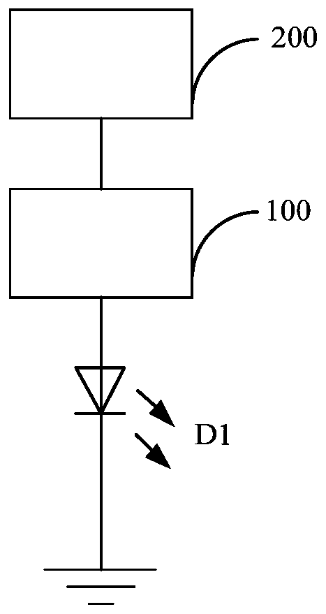
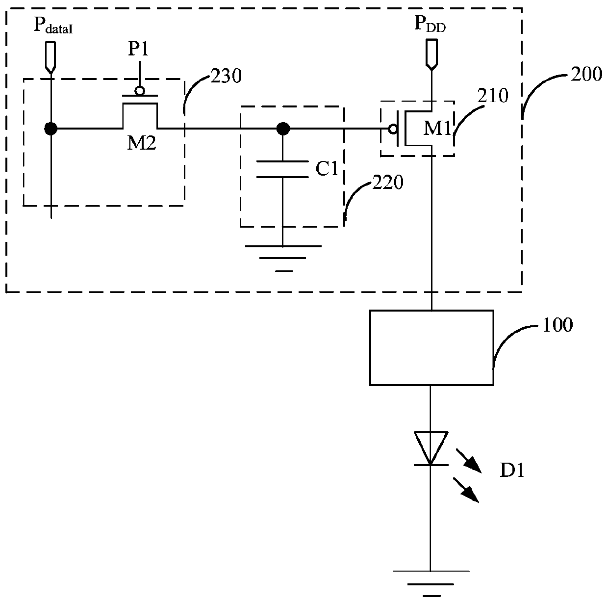
[0031] figure 1 is a schematic structural diagram of a pixel driving circuit according to an embodiment of the present invention. Such as figure 1 As shown, the pixel driving circuit of the embodiment of the present invention may include a micro light emitting diode D1 , a light emission control circuit 100 and a current control circuit 200 .

...


PUM


Abstract

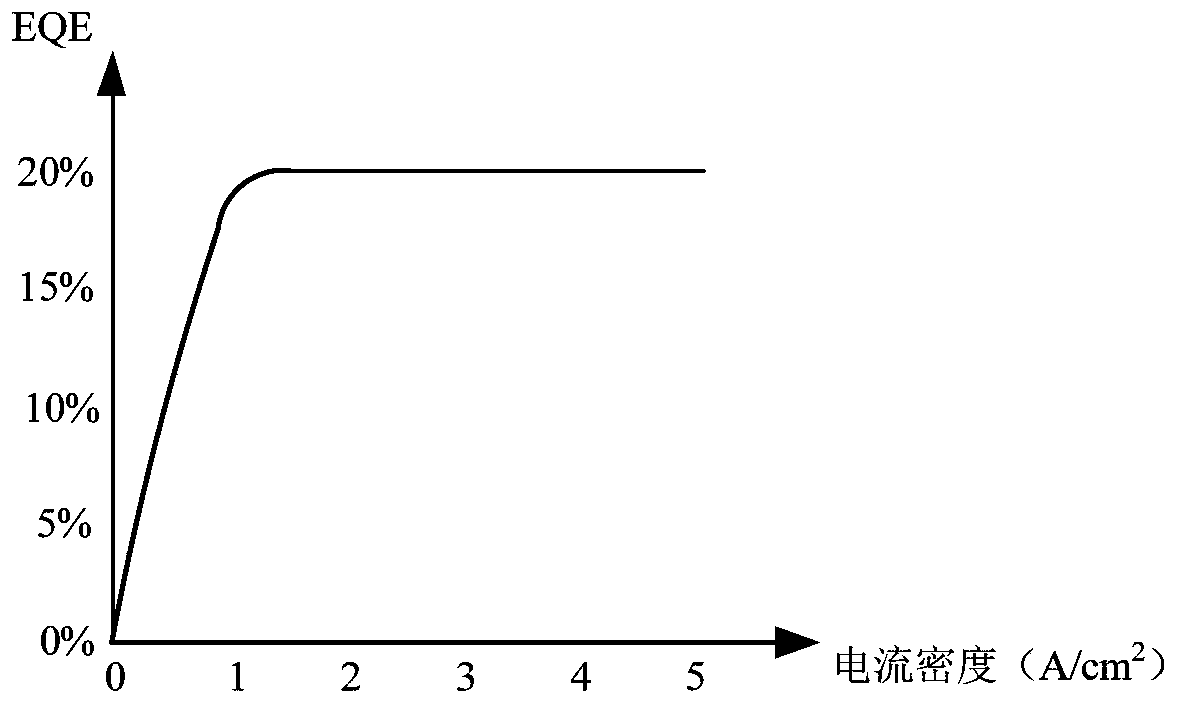
The invention discloses a pixel driving circuit and a display panel, the pixel driving circuit comprises: a micro light-emitting diode, wherein the cathode of the micro light-emitting diode is grounded; a light-emitting control circuit which is connected with the anode of the micro light-emitting diode and is used for controlling the light-emitting duration of the micro light-emitting diode; and acurrent control circuit which is connected with the light-emitting control circuit and is used for outputting a preset current to the light-emitting control circuit so as to control the micro light-emitting diode to work under a set current density, wherein the light-emitting efficiency of the micro light-emitting diode under the set current density is greater than a set threshold value. Therefore, the micro light-emitting diode can be controlled to work in a high current density region all the time; the light-emitting efficiency of the micro-light-emitting diode is ensured, so that the working stability of the micro-light-emitting diode is improved, the light-emitting duration of the micro-light-emitting diode can be accurately and effectively controlled, the brightness and the gray scale of the micro-light-emitting diode are controlled, and the user experience is greatly improved.

Description

technical field [0001] The present invention relates to the display technology field of micro light emitting diodes, in particular to a pixel driving circuit and a display panel. Background technique [0002] With the continuous development of display technology, people's requirements on the resolution, brightness, color saturation, etc. of the display panel are also constantly increasing. Micro-LED, that is, micro-light-emitting diode, is widely used in display panels because of its high brightness, high efficiency, fast response time, small size, long life and many other advantages. [0003] However, in the related art, the brightness and gray scale of the micro-light emitting diode cannot be accurately and effectively controlled, and the stability of the micro-light-emitting diode is relatively poor, thereby greatly reducing user experience. Contents of the invention [0004] The present invention aims to solve one of the technical problems in the related art at least ...

Claims


Application Information

Patent Timeline
IPC IPC(8): G09G3/32
CPCG09G3/32G09G2320/0271G09G2320/0626G09G2300/0852G09G2310/061G09G2300/0861G09G2300/0819G09G3/2014G09G3/2011G09G3/2081G09G2310/066G09G3/2007
Inventor 丛宁杨明岳晗王灿张粲赵蛟玄明花陈小川
Owner BOE TECH GRP CO LTD
Learn More