Motor rotating shaft protection device

A protection device and motor shaft technology, applied in electromechanical devices, cooling/ventilation devices, electrical components, etc., can solve the problems of shortening the service life of the motor shaft, increasing the rotating friction of the rotating shaft, and large rotating friction of the rotating shaft, and prolonging the service life. , the effect of reducing rotational friction and reducing friction

Inactive Publication Date: 2019-07-05
南京路博利尔精密机械有限公司
View PDF0 Cites 4 Cited by
  • Summary
  • Abstract
  • Description
  • Claims
  • Application Information

AI Technical Summary

Problems solved by technology

[0002] Electromechanical equipment has been widely used in the mechanical field, especially the motor, which plays a vital role in various equipment and fields. The shaft of the motor is an important part connecting the rotating parts. When the motor is working, the motor The rotating shaft often produces a certain axial force and radial force, which easily increases the rotating friction of the rotating shaft, greatly reducing the service life of the motor rotating shaft, and the rotation of the rotating shaft causes the overall vibration of the motor, which further increases the rotating friction of the rotating shaft. It is necessary to protect the shaft of the motor to prolong its service life, so we propose a motor shaft protection device

Method used


Image

  • Motor rotating shaft protection device
  • Motor rotating shaft protection device
  • Motor rotating shaft protection device

Examples


Embodiment Construction

[0017] The following will clearly and completely describe the technical solutions in the embodiments of the present invention with reference to the accompanying drawings in the embodiments of the present invention. Obviously, the described embodiments are only some, not all, embodiments of the present invention.

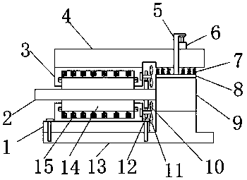
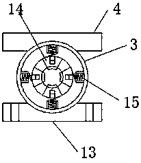
[0018] refer to Figure 1-2 , a motor shaft protection device, including a mounting base 13, the top of the mounting base 13 is fixed with a motor body 9 by bolts, the motor body 9 is rotatably connected with a shaft body 2, and the end of the shaft body 2 close to the motor body 9 is fixed with a first The gear 10, the top of the installation base 13 is fixed with the base plate 1 by bolts, the base plate 1 is welded with the sleeve 3, and the sleeve 3 is slidingly connected with four evenly distributed splints 14, and the sleeve 3 is sleeved on the rotating shaft through the four splints 14 On the main body 2, the first spring 15 is evenly distributed on the side w...


PUM


Abstract

The invention discloses a motor rotating shaft protection device. The device comprises an installation pedestal, and the top of the installation pedestal is fixedly provided with a motor body througha bolt. The motor body is rotationally connected with a rotating shaft body, and one end, close to the motor body, of the rotating shaft body is fixedly provided with a first gear. A bottom plate is fixed at the top end of the installation pedestal through a bolt. A sleeve is welded on the bottom plate, and four clamping plates which are uniformly distributed are connected in the sleeve in a sliding manner. The sleeve is disposed on the rotating shaft body in a sleeving mode through four clamping plates, and first springs are evenly distributed on side walls, away from the rotating shaft body,of the clamping plates, wherein the other ends of the first springs are connected to the inner wall of the sleeve, and a plurality of evenly-distributed rotating rods are rotationally connected to the side wall of the end, close to the motor body, of the sleeve. The device is simple in structure and novel in design, can effectively reduce rotation friction of the motor rotating shaft, prolongs the service life, has a heat dissipation function, can protect the motor, and is high in practicability.

Description

technical field [0001] The invention relates to the technical field of motor shaft protection, in particular to a motor shaft protection device. Background technique [0002] Electromechanical equipment has been widely used in the mechanical field, especially the motor, which plays a vital role in various equipment and fields. The shaft of the motor is an important part connecting the rotating parts. When the motor is working, the motor The rotating shaft often produces a certain axial force and radial force, which easily increases the rotating friction of the rotating shaft, greatly reducing the service life of the motor rotating shaft, and the rotation of the rotating shaft causes the overall vibration of the motor, which further increases the rotating friction of the rotating shaft. It is necessary to protect the rotating shaft of the motor to prolong its service life, so we propose a motor rotating shaft protection device. Contents of the invention [0003] The object...

Claims


Application Information

Patent Timeline
Patent Type & Authority Applications(China)
IPC IPC(8): H02K7/00H02K9/06H02K5/24
CPCH02K5/24H02K7/003H02K9/06
Inventor 不公告发明人
Owner 南京路博利尔精密机械有限公司
Why Eureka
Try Eureka