
Waveform shaping circuit and electronic equipment

A waveform shaping and circuit technology, applied in the direction of pulse shaping, etc., can solve problems such as the limitation of application of wave shaping circuits

Active Publication Date: 2019-07-05
上海林果实业股份有限公司
View PDF11 Cites 2 Cited by
  • Summary
  • Abstract
  • Description
  • Claims
  • Application Information

AI Technical Summary

Problems solved by technology

[0004] The purpose of the embodiments of the present invention is to provide a waveform shaping circuit and electronic equipment, which can not only perform waveform shaping on signals through a simple circuit structure, but also solve the limitation of the application of the waveform shaping circuit in the prior art

Method used


Image

  • Waveform shaping circuit and electronic equipment
  • Waveform shaping circuit and electronic equipment
  • Waveform shaping circuit and electronic equipment

Examples


Embodiment Construction

[0023] In order to make the purpose, technical solutions and advantages of the embodiments of the present invention more clear, various implementation modes of the present invention will be described in detail below in conjunction with the accompanying drawings. However, those of ordinary skill in the art can understand that, in each implementation manner of the present invention, many technical details are provided for readers to better understand the present application. However, even without these technical details and various changes and modifications based on the following implementation modes, the technical solution claimed in this application can also be realized.

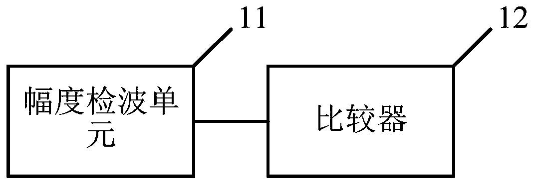
[0024] A first embodiment of the present invention relates to a waveform shaping circuit. Such as image 3 , Figure 4 As shown, it includes: an amplitude detection unit 11 and a comparator 12; the waveform input terminal is connected to the first input terminal of the comparator 12; one end of the amplitu...


PUM


Abstract

The embodiment of the invention relates to the technical field of electronic circuits, and discloses a waveform shaping circuit and electronic equipment. The waveform shaping circuit comprises: an amplitude detection unit and a comparator, wherein the waveform input end is connected with the first input end of the comparator; one end of the amplitude detection unit is connected with the waveform input end, and the other end of the amplitude detection unit is connected with the second input end of the comparator; an amplitude detection unit which is used for receiving the input voltage of the waveform input end and generating a reference voltage in direct proportion to the amplitude of the input voltage; and a comparator which is used for receiving the reference voltage and the input voltage of the waveform input end, comparing the input voltage with the reference voltage and outputting a level signal after waveform shaping. The embodiment of the invention further provides electronic equipment. Not only can waveform shaping be performed on a signal through a simple circuit structure, but also the problem of application limitation of a waveform shaping circuit in the prior art can besolved.

Description

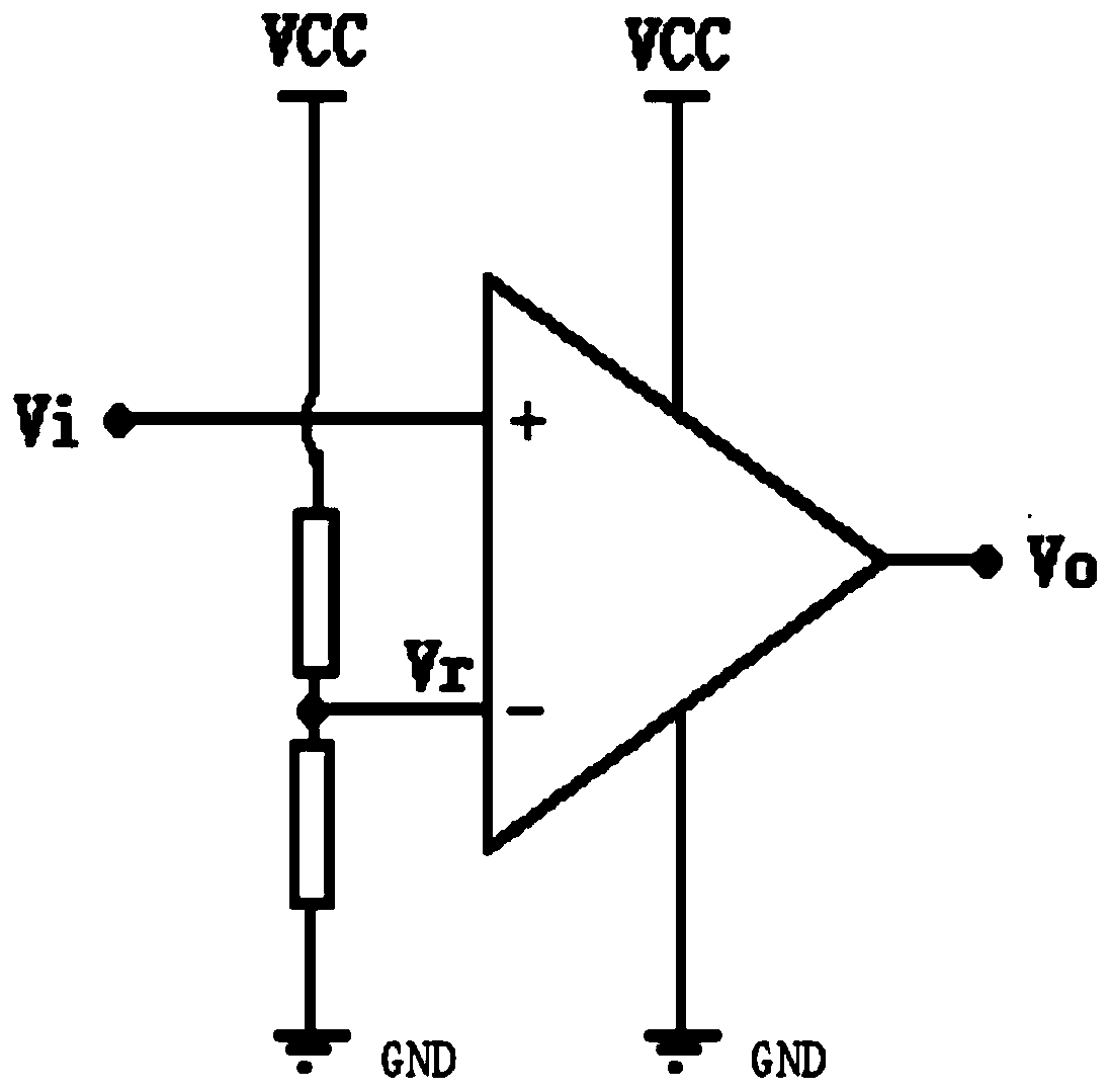
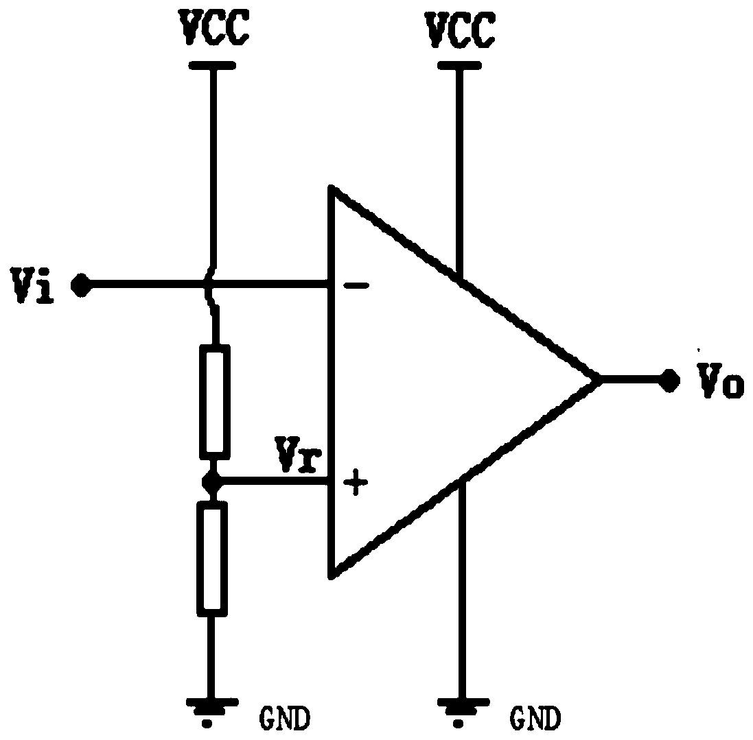
technical field [0001] Embodiments of the present invention relate to the technical field of electronic circuits, in particular to a waveform shaping circuit and electronic equipment. Background technique [0002] Signal waveform shaping is widely used in modern electronic technology, and the most commonly used is to shape non-square wave signals (such as sine wave signals) into square wave signals so that digital systems can recognize and process them. Traditional square wave shaping circuits such as figure 1 , figure 2 As shown: the signal Vi to be shaped is input to one of the input terminals of the comparator, and the other input terminal of the comparator is connected to a fixed voltage Vr as a reference voltage. When the signal Vi to be shaped rises above the reference voltage Vr or falls below the reference voltage Vr, the output level of the output terminal of the comparator is reversed, thereby outputting the square wave signal Vo of the signal Vi to be shaped. ...

Claims


Application Information

Patent Timeline
Patent Type & Authority Applications(China)
IPC IPC(8): H03K5/01
CPCH03K5/01
Inventor 白清顺
Owner 上海林果实业股份有限公司
Learn More