
Automatic detection and screening system with multiple conveying disks

An automatic detection and conveying tray technology, applied in sorting and other directions, can solve problems such as dust or impurities blowing in, single image, damage, etc., to improve detection accuracy and precision, avoid missed or wrong detection, and ensure detection quality Effect

Active Publication Date: 2019-07-09
东莞市雅创自动化科技有限公司
View PDF8 Cites 8 Cited by
  • Summary
  • Abstract
  • Description
  • Claims
  • Application Information

AI Technical Summary

Problems solved by technology

[0011] (2) In the existing detection and screening system, after the detection object enters the glass feeding tray, it is still relative to the glass feeding tray, and will not change its position and angle, so that the image of the part collected by the phase acquisition and detection device is single, and the image of the part changing angle cannot be collected. Therefore, it may not be possible to collect all the useful information of the detected object
[0012] (3) In the existing detection and screening system, whether it is a good product unloading device or a defective product unloading device, the detection object is blown away from the glass feeding tray through high-pressure gas, but for some highly sensitive, high-precision and high-standard detection objects, such as : Mobile phone camera accessories, blowing air may blow dust or impurities into the detection object, causing the detection object to fail to work or even be damaged

Method used


Image

  • Automatic detection and screening system with multiple conveying disks
  • Automatic detection and screening system with multiple conveying disks
  • Automatic detection and screening system with multiple conveying disks

Examples


Embodiment Construction

[0048] Combine below Figure 1 to Figure 8 , the present invention is further described:

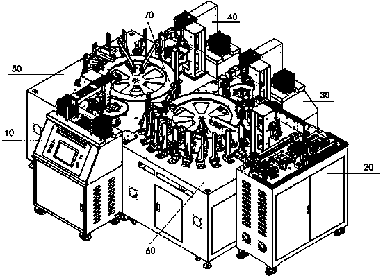
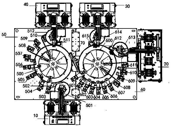
[0049] Such as figure 1 As shown, the automatic detection and screening system of the multi-transport tray of the present invention includes a feeding device 10, a first unloading device 20, a second unloading device 30, a third unloading device 40, a first detection unit 50 and a second detection unit Unit 60.

[0050] The feeding device 10 guides the object to be detected into the first rotating disk body of the first detection unit 50, and multiple phase detection devices in the first detection unit 50 around the first rotating disk body take pictures of the detection object from different directions , the object to be detected enters the second rotating disc body of the second detecting unit 60 through the connecting mechanism between the first detecting unit 50 and the second detecting unit 60, and a plurality of pick-ups in the second detecting unit 60 around the second rotating ...


PUM


Abstract

The invention relates to an automatic detection and screening system with multiple conveying disks. A feeding device (10) guides an object to be detected into a first rotary disk body (500) of a firstdetection unit (50). A plurality of photographing detection devices on the periphery of the first rotary disk body (500) conduct photographing on the object to be detected in different directions. The object to be detected gets into a second rotary disk body (600) of a second detection unit (60) through a connecting mechanism from the first rotary disk body of the first detection unit (50). A plurality of photographing detection devices on the periphery of the second rotary disk body conduct photographing on the object to be detected in the different directions. A computer analyzes and judgeswhether the object to be detected is a good product or a defective product according to pictures photographed by the photographing detection devices. Defective products detected by the first detection unit are discharged through a third discharging device (40). Defective products detected by the second detection unit are discharged through a second discharging device (30). Good products detectedby the second detection unit are discharged through a first discharging device (20).

Description

technical field [0001] The invention relates to a material detection and screening system, in particular to an automatic detection and screening system for multiple conveying trays. Background technique [0002] In the development of the electronics industry, due to the global development trend of light and thin electronic products, the specifications and sizes of various parts used such as screws, nuts, rivets, stamping parts, plastic parts and even camera motors have also been miniaturized. Generally speaking, parts that are defective or do not meet the requirements will not only cause the failure of normal installation, but also cause damage to other parts when they are installed and used forcibly. They will go through the screening and testing of good and bad quality, in order to maintain the good quality and efficiency of fastening between product components, and reduce the probability of defective products caused by abnormal fasteners. [0003] In the prior art, autom...

Claims


Application Information

Patent Timeline
Patent Type & Authority Applications(China)
IPC IPC(8): B07C5/00B07C5/02B07C5/36
CPCB07C5/00B07C5/02B07C5/362B07C2501/0063
Inventor 邓卫国
Owner 东莞市雅创自动化科技有限公司
Learn More