
Contamination and defect resistant rotary optical encoder construction for providing displacement signals

A technology of optical encoders and displacement signals, which is applied in the direction of converting sensor output, instruments, measuring devices, etc., and can solve problems such as less than ideal and complex signal processing

Active Publication Date: 2021-04-06
MITUTOYO CORP
View PDF27 Cites 0 Cited by
  • Summary
  • Abstract
  • Description
  • Claims
  • Application Information

AI Technical Summary

Problems solved by technology

However, the '572 patent relies on complex signal processing, which may not be ideal in some applications

Method used


Image

  • Contamination and defect resistant rotary optical encoder construction for providing displacement signals
  • Contamination and defect resistant rotary optical encoder construction for providing displacement signals
  • Contamination and defect resistant rotary optical encoder construction for providing displacement signals

Examples


Embodiment Construction

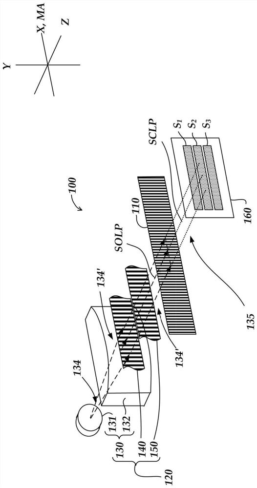
[0035] figure 1 is a partially exploded schematic view of an optical encoder configuration 100 for providing displacement signals resistant to contamination and imperfections. The encoder configuration 100 includes a scale grating 110 , an illumination portion 120 and a light detector configuration 160 .

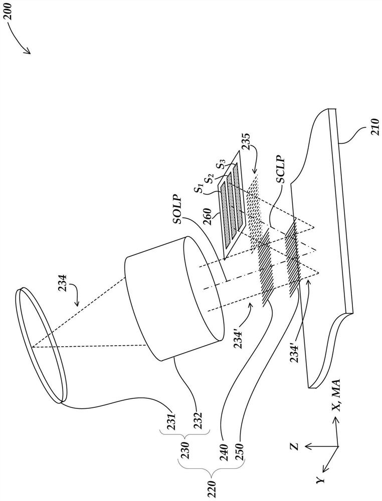
[0036] figure 1 Orthogonal X, Y, and Z directions are shown according to the convention used here. The X and Y directions are parallel to the plane of the scale grating 110, the X direction being parallel to the measurement axis direction MA (eg, perpendicular to the elongated pattern elements of the scale grating 110). The Z direction is perpendicular to the plane of the scale grating 110 .

[0037] exist figure 1 In the illustrated embodiment, the scale grating 110 is a transmissive grating. The scale grating 110 extends along the measurement axis direction MA and comprises a periodic pattern comprising strips that are narrower along the measurement axis direction MA ...


PUM


Abstract

A contamination and defect resistant rotary optical encoder configuration for providing a displacement signal is provided that includes a rotary scale, an illumination source, and a photodetector configuration. The illumination source is configured to output collimated light to the scale at a first illumination area, which light is subsequently output to the scale at a second illumination area from which the scale outputs scale light forming a detector fringe pattern, the detection The detector fringe pattern consists of periodic bands of high and low intensity that extend in a relatively long dimension along the rotational measurement direction and are relatively narrow and periodic along the direction of detected fringe motion transverse to the rotational measurement direction . As the scale grating is displaced in the direction of rotational measurement, the high and low intensity bands move in the direction of the detected fringe motion. The photodetector configuration is configured to detect the displacement of the high-intensity band and the low-intensity band and provide a corresponding spatial phase displacement signal indicative of the displacement of the rotating scale.

Description

[0001] Cross References to Related Applications [0002] This application is a continuation-in-part of U.S. Patent Application Serial No. 15 / 942,135, filed March 30, 2018, entitled "CONTAMINATION AND DEFECT RESISTANTOPTICAL ENCODER CONFIGURATION FOR PROVIDING DISPLACEMENT SIGNALS," which was filed December 29, 2017 A continuation-in-part of U.S. Patent Application Serial No. 15 / 858,218, entitled "CONTAMINATION AND DEFECT RESISTANT OPTICAL ENCODER CONFIGURATION FORPROVIDING DISPLACEMENT SIGNALS"; this patent application is a continuation-in-part of the application titled "CONTAMINATION AND DEFECT RESISTANTOPTICAL ENCODER CONFIGURATION FOR PROVIDING DISPLACEMENT SIGNALS", a continuation-in-part of US Patent Application Serial No. 15 / 702,520, filed June 29, 2017, entitled "CONTAMINATION AND DEFECT RESISTANT OPTICAL ENCODER CONFIGURATION FOR PROVIDING DISPLACEMENT SIGNALS" Continuation-in-Part Application Serial No. 15 / 637,750, the disclosures of which are hereby incorporated by ref...

Claims


Application Information

Patent Timeline
Patent Type & Authority Patents(China)
IPC IPC(8): G01D5/347
CPCG01D5/3473G01D5/34715
Inventor J.D.托比亚森
Owner MITUTOYO CORP
Learn More