
Self-excited moisture flow measuring device

A flow measuring device and self-exciting technology, applied in the direction of volume flow measuring device, measuring device, fixed measuring chamber, etc., can solve the problems of difficult to achieve accuracy, difficult to meet user requirements, low liquid content, etc., and achieve convenient detection. Effect

Pending Publication Date: 2019-07-09
WUXI SEA PIONEERS TECH CO LTD
View PDF0 Cites 1 Cited by
  • Summary
  • Abstract
  • Description
  • Claims
  • Application Information

AI Technical Summary

Problems solved by technology

A large number of studies have shown that the false high characteristic of the differential pressure flowmeter has good repeatability, so the corresponding correction model can be used to correct it, so as to obtain the real gas phase flow rate; the measurement of the gas phase flow rate needs to be obtained through a large number of experiments Correct the model data accordingly, so the overall design is very responsible
[0004] At the same time, in the process of measuring the liquid phase medium, because its liquid content is at a relatively low level, if it is necessary to ensure a good accuracy in liquid phase measurement, the accuracy of an instrument is very high, so that it is difficult to meet the needs of users
For example, in the state of 5% liquid content, in order to achieve the accuracy of the liquid volume measurement accuracy not less than 1%, the gas-liquid phase ratio needs to reach the accuracy of 0.05*0.01=0.0005, the lower the liquid content, the other The higher the accuracy requirements, however, in practice, such a high accuracy is difficult to achieve, so there is room for improvement in the measurement equipment for gas phase flow and liquid phase flow

Method used


Image

  • Self-excited moisture flow measuring device
  • Self-excited moisture flow measuring device
  • Self-excited moisture flow measuring device

Examples


Embodiment Construction

[0033] The present invention will be described in further detail below in conjunction with the accompanying drawings.

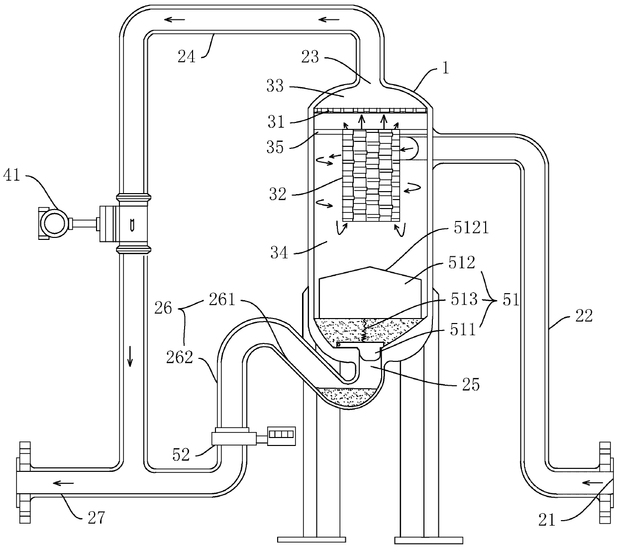
[0034] refer to figure 1 , is a self-excited wet gas flow measuring device disclosed in the present invention. The measuring device can separate the wet gas into dry gas and liquid, and simultaneously measure the two separately. The whole measuring method is simple and novel, and the operation is feasible High performance, the separation of gas and liquid can be detected and measured more accurately without mutual interference.

[0035] like figure 1 As shown, the self-excited wet gas flow measurement device specifically includes a housing 1. The cross section of the housing 1 can be in different shapes such as square, circular, rhombus, etc. In this embodiment, the housing 1 with a circular cross section is preferably used. That is, the housing 1 is cylindrical, and the housing 1 is installed vertically.

[0036] like figure 1 As shown, the housing 1 is ...


PUM


Abstract

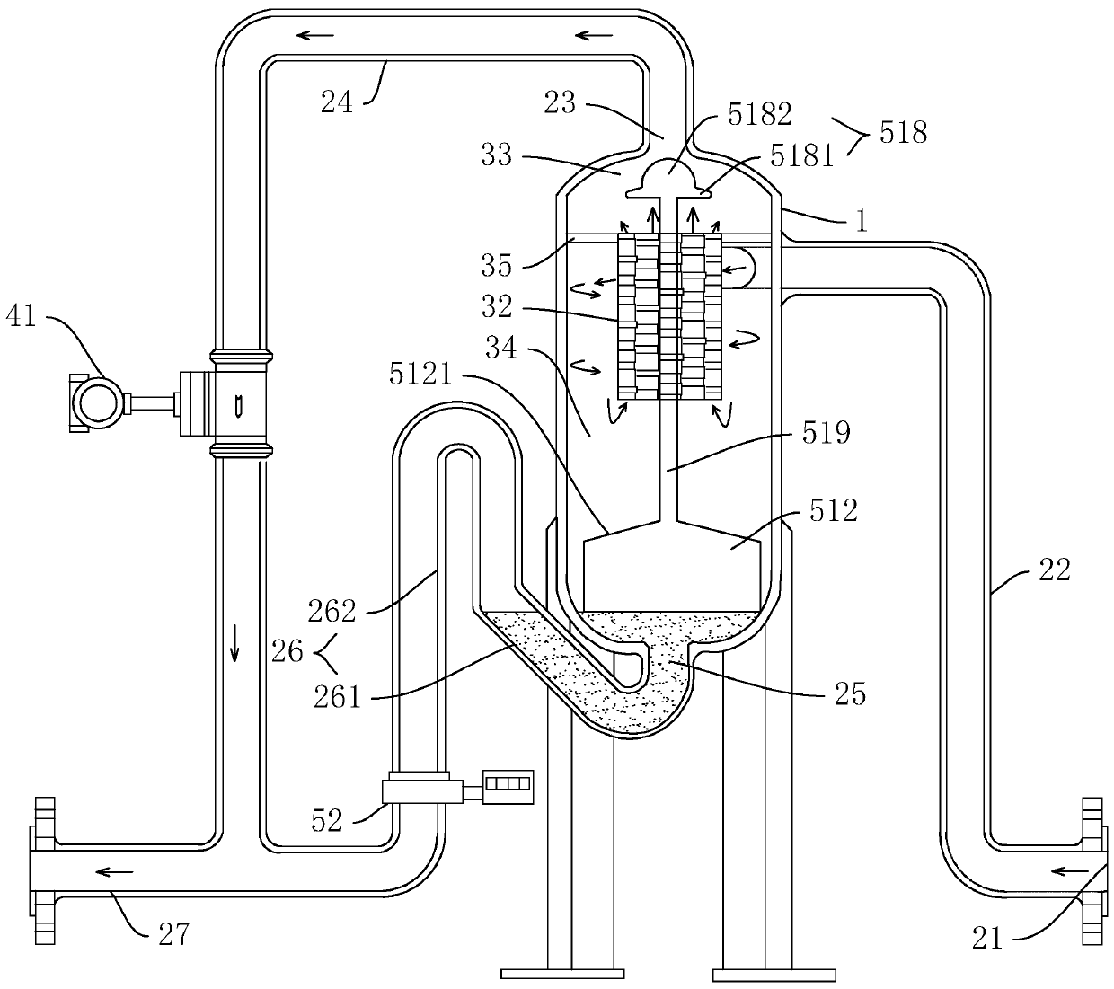
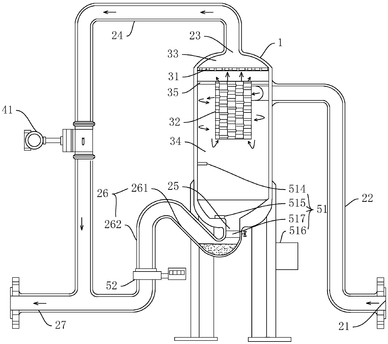
The invention relates to a self-excited moisture flow measuring device, which includes a shell. The shell is provided with a wet gas inlet for introducing wet gas, a dry gas outlet for outputting drygas and a liquid outlet for outputting liquid, a mist catching filter screen for separating an cavity inside the shell into a dry gas area and a wet gas area is installed in the middle of the shell, the wet gas inlet and the liquid outlet are both formed in the wet gas area, the dry gas outlet is formed in the dry gas area, the dry gas outlet is provided with a gas flowmeter for measuring the transmitted dry gas, a control device for controlling the liquid outlet to open and close and outputting the liquid quantitatively is arranged in the wet gas area, and the liquid outlet is provided with adetection and counting device for detecting whether liquid output exists or not and counting. According to the self-excited moisture flow measuring device, a principle of hydrocyclone separation canbe used, separate measurement of the gas and liquid is realized, measurement of the liquid quantity is realized through statistics of the number of times of liquid discharging, more accuracy is achieved, and detection is convenient.

Description

technical field [0001] The invention relates to the technical field of moisture measurement, in particular to a self-excited moisture flow measurement device. Background technique [0002] In the process of oil and gas production, wet gas is a common form. Measuring wet gas to obtain the flow rate of gas and liquid is the demand of oil and gas production. Moisture is a special form of gas-liquid two-phase flow, which widely exists in industrial production processes. It is generally believed that in gas-liquid two-phase flow, the flow state when the gas phase is the continuous phase and the liquid phase is the discrete phase is wet. Gas, moisture generally refers to the volume of liquid content of less than 5%. The flow and distribution of the gas-liquid two-phase in the tube is called the flow pattern. The flow pattern is an intuitive reflection of the energy state and interaction of the gas-liquid two-phase. Due to the large differences in the density, velocity, and viscos...

Claims


Application Information

Patent Timeline
Patent Type & Authority Applications(China)
IPC IPC(8): G01F7/00G01F11/32G01F1/00B01D50/00B01D46/24B01D46/10B01D46/00
CPCG01F7/00G01F11/32G01F1/00B01D46/0012B01D46/10B01D46/2411B01D46/62B01D50/20G01F3/30G01F15/125G01F15/08B01D45/16G01F15/005
Inventor 徐斌罗超李敬阳陈继革
Owner WUXI SEA PIONEERS TECH CO LTD
Learn More