Receiving device, mobile terminal, and barcode reading control method

A mobile terminal and barcode technology, applied in electromagnetic radiation induction, instruments, induction record carriers, etc., can solve the problems of long payment time, poor user experience, and affecting payment speed, so as to reduce learning costs and improve user experience.

Pending Publication Date: 2019-07-09
CHINA UNIONPAY
View PDF7 Cites 2 Cited by
  • Summary
  • Abstract
  • Description
  • Claims
  • Application Information

AI Technical Summary

Problems solved by technology

[0008] The shortcomings of the existing technology are: user operations are required, the process is cumbersome, and the user experience is poor; the payment takes too long, especially when the user is not familiar with the operation process of scanning the code, and when many people are waiting for payment, the payment speed is affected ;The existing code scanning device is a handheld code scanning device / fixed code scanning device. The handheld code scanning device requires the cashier to hold the device close to the user terminal, and the fixed code scanning device requires the user to bring the mobile phone close to the code scanning device.
Scanning codes on handheld devices requires the cooperation of users and cashiers. Scanning codes on fixed devices requires users to have a certain understanding of the range of code scanning, and there is a certain learning cost for scanning codes.

Method used


Image

  • Receiving device, mobile terminal, and barcode reading control method
  • Receiving device, mobile terminal, and barcode reading control method
  • Receiving device, mobile terminal, and barcode reading control method

Examples


Embodiment Construction

[0057] Introduced below are some of the various embodiments of the invention, intended to provide a basic understanding of the invention. It is not intended to identify key or critical elements of the invention or to delineate the scope of protection.

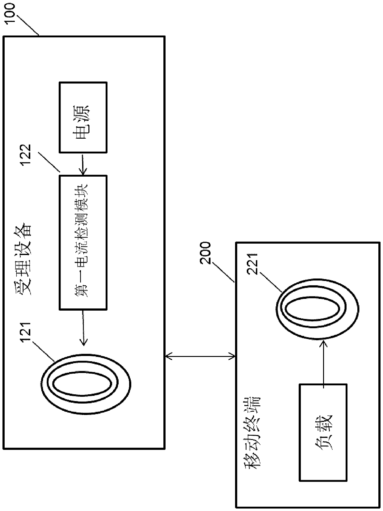
[0058] figure 1 is a schematic diagram showing the configuration of the reception system of the present invention. Such as figure 1 As shown, the acceptance system in one aspect of the present invention includes an acceptance device 100 and a mobile terminal 200 .

[0059] Wherein, the receiving device 100 includes:

[0060] The camera 110 is used to scan the barcode displayed by the mobile terminal 200;

[0061] The first detection module 120 is configured to detect whether the mobile terminal 200 is close to the camera, for example, detect whether the mobile terminal 200 is placed in the camera range area of ​​the camera of the acceptance terminal 100;

[0062] The first main control processor 130 controls the camera 110...


PUM


Abstract

The invention relates to a receiving device and a mobile terminal. The receiving device comprises a camera used for scanning a bar code displayed by the mobile terminal; a first detection module usedfor detecting whether the mobile terminal is placed in a camera shooting range area of the camera or not; and a first main control processor used for controlling the camera to open and scan the bar code when the first detection module detects that the mobile terminal is placed in the camera shooting range area of the camera. The mobile terminal comprises a bar code function module used for displaying a bar code; the second detection module is used for detecting whether the mobile terminal is placed in a camera shooting range area of the camera or not; and the second main control processor is used for controlling the bar code function module to display the bar code when the second detection module detects that the mobile terminal is placed in the camera shooting range area of the camera. According to the invention, when the mobile terminal is placed in the scannable range of the camera of the accepting device, an interface needing to be scanned can be immediately opened on the display screen of the mobile terminal.

Description

technical field [0001] The invention relates to mobile payment technology, in particular to an acceptance device and a barcode reading control method capable of enabling a mobile terminal to quickly display a two-dimensional code. Background technique [0002] In recent years, QR code payment has become a very popular payment method, but the existing payment methods have certain disadvantages in terms of experience. The user needs to open the application program with the payment function on the electronic device, the initial page of the application program can be displayed on the display screen of the electronic device, and the user clicks the "payment" button on the initial page of the application program, and the electronic device will display the payment authorization code of the user. (QR code) page. The payment process is cumbersome and the user experience is not good. [0003] For example, in a specific example, the process of invoking a QR code is as follows: [00...

Claims


Application Information

Patent Timeline
Patent Type & Authority Applications(China)
IPC IPC(8): G06K7/10
CPCG06K7/10831G06K7/10881
Inventor 余玮琦万四爽邱雪涛何朔
Owner CHINA UNIONPAY
Why Eureka
Try Eureka