Unlock instant, AI-driven research and patent intelligence for your innovation.

Rotation device

A technology of rotating device and connecting piece, applied in the field of transmission, can solve the problems of unfavorable strength calculation, uneven bolt arrangement of flange, low reliability of bolt connection, etc., and achieve the effect of improving reliability and uniform force

Active Publication Date: 2019-07-09
HUAWEI TECH CO LTD
View PDF27 Cites 0 Cited by
  • Summary
  • Abstract
  • Description
  • Claims
  • Application Information

AI Technical Summary

Problems solved by technology

In the prior art, in order to realize the function of adjusting the angle of the overall structure of the antenna, it is necessary to set up arc bolt holes on the flange plate at the bottom of the antenna pole. When the adjustment angle is large, the length of the arc bolt holes will also increase. In addition, , a large area of ​​cable holes is opened on the flange, and due to the need for rotation, the ends of the arc bolt holes cannot be provided with bolts, which will cause uneven bolt layout on the flange, which is very unfavorable in strength calculation , making bolted connections less reliable

Method used


Image

  • Rotation device
  • Rotation device
  • Rotation device

Examples


Embodiment Construction

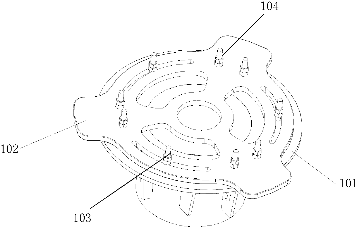
[0026] The embodiment of the present application provides a rotating device, and the rotation is realized through the cooperation of two flanges, which improves the reliability of the rotatable connection.

[0027] The following will clearly and completely describe the technical solutions in the embodiments of the application with reference to the drawings in the embodiments of the application. Apparently, the described embodiments are only some of the embodiments of the application, not all of them. The terms "first", "second", "third", "fourth", etc. (if any) in the specification and claims of the present application and the above drawings are used to distinguish similar objects, and not necessarily Used to describe a specific sequence or sequence. It is to be understood that the terms so used are interchangeable under appropriate circumstances such that the embodiments described herein can be practiced in sequences other than those illustrated or described herein. Furtherm...


PUM


Abstract

The embodiment of the invention discloses a rotation device. The rotation device comprises a first flange disc, a second flange disc, a first connection piece and a second connection piece, wherein afirst through hole and a first rail groove are formed in the first flange disc, a second through hole and a second rail groove are formed in the second flange disc, the first connection piece penetrates through the first through hole and the second rail groove, the second connection piece penetrates through the first rail groove and the second through hole, when the first flange disc or the secondflange disc rotates, the first connection piece moves in the second rail groove, and the second connection piece moves in the first rail groove. The stress of the first flange disc and the second flange disc can be more uniform as well as integral rotation is achieved, so that the connection reliability is improved.

Description

technical field [0001] The present application relates to the transmission field, in particular to a rotating device. Background technique [0002] In the iron tower base station, in order to achieve the beautification effect of the iron tower, the pole is connected to the tower on the top of the tower through the flange, and then the antenna or radio remote unit (radio remote unit, RRU) equipment and other equipment are installed on the pole, which can reduce the The installation volume of the antenna and other equipment can be coordinated and unified with the tower body after adding a camouflage cover to achieve a beautifying effect. However, since the directional antenna needs to adjust the direction angle, the existing technology realizes the angle adjustment of a single antenna by adjusting the connection between the antenna and the pole, and the flange connecting the antenna section and the iron tower is a fixing bolt hole, which cannot be rotated as a whole. Therefor...

Claims


Application Information

Patent Timeline
Patent Type & Authority Applications(China)
IPC IPC(8): H01Q1/12H01Q3/04
CPCH01Q1/1207H01Q3/04
Inventor 罗澎赵志雄万云冬张志宏危文杰
Owner HUAWEI TECH CO LTD
Features
  • R&D
  • Intellectual Property
  • Life Sciences
  • Materials
  • Tech Scout
  • Unparalleled Data Quality
  • Higher Quality Content
  • 60% Fewer Hallucinations
Learn More