Waste collecting equipment and waste collecting and treatment system

A technology for collecting equipment and waste, which is applied in surgical equipment, extraction and delivery systems, medical science, etc., can solve the problems of slow transfer speed, affecting the progress and fluency of surgery, and slow speed, so as to achieve fast transfer speed and surgical treatment Smooth and smooth, avoiding the effect of operation interruption

Pending Publication Date: 2019-07-12
AMSINO MEDICAL (SHANGHAI) CO LTD
View PDF0 Cites 4 Cited by
  • Summary
  • Abstract
  • Description
  • Claims
  • Application Information

AI Technical Summary

Problems solved by technology

However, in this technical scheme, since the two chambers are connected with the same negative pressure source, in the operation of transferring the waste in the small chamber to the large chamber, since the pressure of the two is the same, the transfer method of self-flow will reduce the speed. Slower, but because many operations cannot be delayed, this technical solution will bring very adverse effects when performing some operations; for other operations, it will also greatly affect the progress of the operation because of the slow transfer speed and fluency, causing a lot of inconvenience to patients and medical staff

Method used


Image

  • Waste collecting equipment and waste collecting and treatment system
  • Waste collecting equipment and waste collecting and treatment system
  • Waste collecting equipment and waste collecting and treatment system

Examples


Embodiment Construction

[0037] The following descriptions of the various embodiments refer to the accompanying drawings to illustrate specific embodiments in which the present invention can be implemented. The directional terms mentioned in the present invention, such as "up", "down", "front", "back", "left", "right", "inside", "outside", "side", etc., are for reference only The orientation of the attached schema. Therefore, the directional terms used are used to illustrate and understand the present invention, but not to limit the present invention.

[0038] In order to make the purpose, technical solution and advantages of the present invention clearer, the present invention will be further described in detail below with reference to the accompanying drawings.

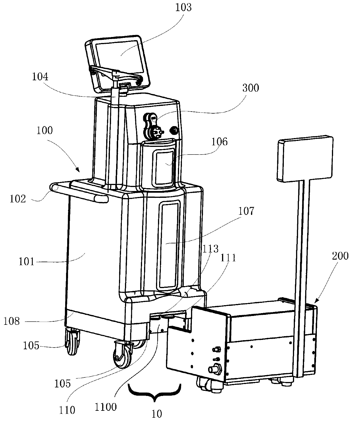
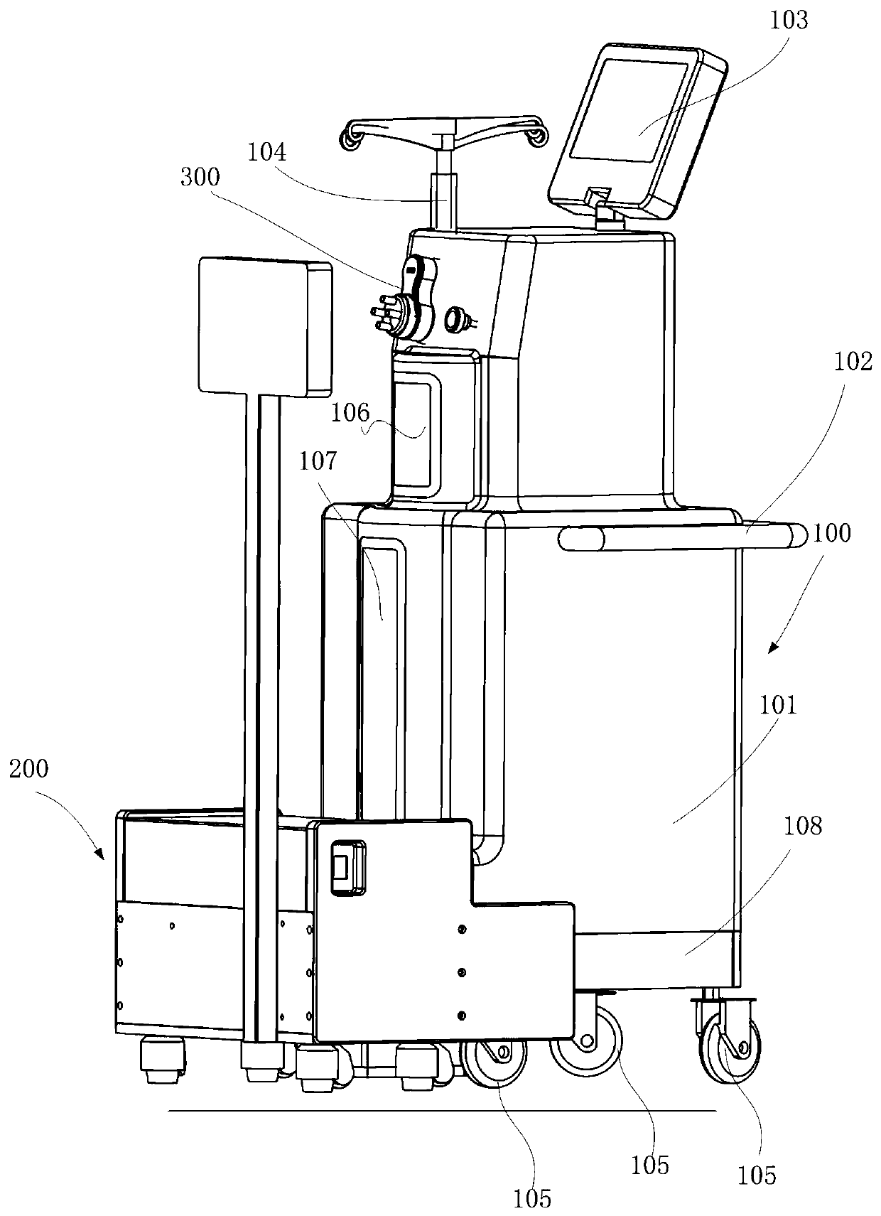
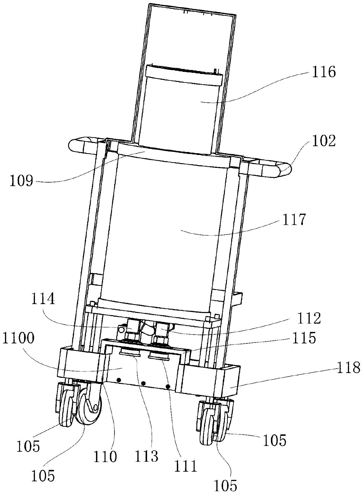
[0039] Such as Figure 1-Figure 4 as shown, figure 1 and figure 2 Shown is a waste collection and treatment system 10 comprising a waste collection device 100 and a docking device 200, figure 1 The waste collection and treatment syste...


PUM


Abstract

The embodiment of the invention provides waste collecting equipment. The equipment comprises a portable trolley, a waste collecting container, a movable valve and a valve controller, wherein the wastecollecting container comprises a first cavity and a second cavity, and the first cavity and the second cavity are connected with the same negative pressure source; a partition wall is arranged between the first cavity and the second cavity; the movable valve is arranged in the waste collecting container, and is used for making the first cavity communicated with or isolated from the second cavity;the valve controller is connected with the movable valve; when waste of the first cavity needs to be transferred to the second cavity, the valve controller controls the movable valve to be communicated with the first cavity and the second cavity, and controls the movable valve to perform emptying operation under the condition that the first cavity body and the second cavity body are communicatedwith each other; after the waste of the first cavity is transferred, the movable valve is controlled to isolate the first cavity from the second cavity. The first cavity can be used for rapidly transferring the waste into the second cavity.

Description

technical field [0001] The invention relates to a waste collection device and a waste collection and treatment system, which are used for collecting and treating waste materials generated in medical procedures. Background technique [0002] During the implementation of specific surgical procedures, liquid, semi-solid and solid wastes will inevitably be generated, including body fluids, such as blood, and perfusion solutions introduced into the surgical site during the surgical process. The solid and semi-solid waste generated includes tissue fragments and small pieces of surgical material that may remain on body parts. Ideally, waste is collected as it is generated so that it neither contaminates the surgical site nor becomes a biohazard in the operating room or other place where surgical procedures are performed. [0003] In the prior art, there are various waste collection and treatment systems for medical staff to collect waste generated during the operation or after the...

Claims


Application Information

Patent Timeline
Patent Type & Authority Applications(China)
IPC IPC(8): A61M1/00B08B3/02A61B50/13
CPCA61B50/13A61M1/0001A61M1/0023B08B3/02
Inventor 梁洪岐栗亚宗玉阳
Owner AMSINO MEDICAL (SHANGHAI) CO LTD
Why Eureka
Try Eureka