
Electric aspirator

A suction device, electric technology, applied in the direction of suction container, suction equipment, pumping and pumping system, etc., can solve the problems of disassembly and installation labor, and achieve the effect of convenient installation and disassembly

Pending Publication Date: 2019-07-12
史灵芝
View PDF0 Cites 0 Cited by
  • Summary
  • Abstract
  • Description
  • Claims
  • Application Information

AI Technical Summary

Problems solved by technology

[0004] For this reason, the embodiment of the present invention provides an electric suction device to solve the problem in the prior art when it is disassembled and installed due to the tight connection of the connecting pipes between the upper covers of the existing electric suction device. will be more difficult

Method used


Image

  • Electric aspirator
  • Electric aspirator
  • Electric aspirator

Examples


Embodiment

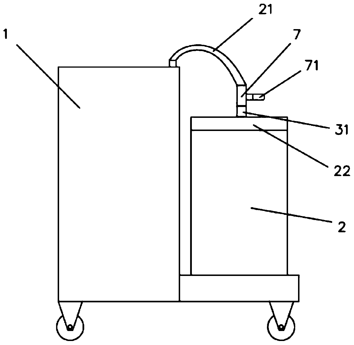
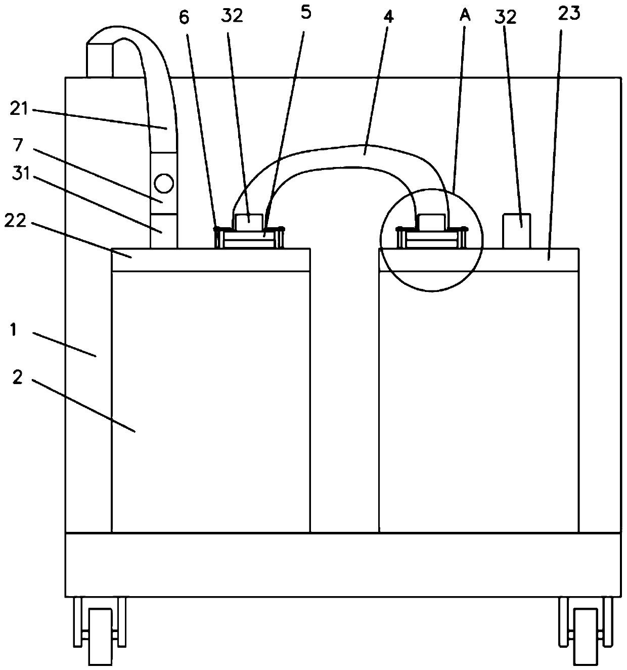
[0021] An electric aspirator such as figure 1 , 2 As shown, the suction device body 1 and two storage barrels 2 are arranged on the suction device. The first cover 22 and the second cover 23 are respectively arranged on the two storage barrels 2. In addition, the first cover 22 and the second cover 23 The second cover 23 is respectively provided with a water inlet pipe 31 and a water outlet pipe 32, and a connecting pipe 4 is connected between the first cover 22, the water outlet pipe 32 and the water inlet pipe 31 on the second cover 23, and in the first A feed pipe 21 is connected between the water inlet pipe 31 of the cover 22 and the aspirator body 1; in this way, after using the aspirator body 1 to suck away some permeate, the permeate can enter the storage barrel along the feed pipe 21 2, after one of the storage barrels 2 is filled with permeate, the permeate can enter the other storage barrel 2 along the connecting pipe 4; after the permeate in the two storage barrels...


PUM


Abstract

The embodiment of the invention discloses an electric aspirator, and belongs to the technical field of medical instruments. The electric aspirator comprises an aspirator body, two storage barrels on the aspirator body, a first sealing cover and a second sealing cover, wherein the first sealing cover and the second sealing cover are arranged on the two storage barrels, a water inlet pipe and a water outlet pipe are arranged on the first sealing cover and the second sealing cover respectively, and a connecting pipe is connected between the water outlet pipe of the first sealing cover and the water inlet pipe of the second sealing cover; a feeding pipe is connected between the water inlet pipe of the first sealing cover and the aspirator body, the two ends of the connecting pipe are both provided with an annular positioning piece, and fixing pieces are fixedly connected to the bottom of the water inlet pipe of the second sealing cover and the bottom of the water outlet pipe of the first sealing cover; the two ends of the connecting pipe are inserted into the water inlet pipe and the water outlet pipe, the positioning pieces abut against the fixing pieces, and a plurality of vertical rods are arranged on the upper surface of the first sealing cover and the upper surface of the second sealing cover; the vertical rods are uniformly distributed around the circumferences of the fixingpieces, a pressing rod is rotationally connected to the upper end of each vertical rod, and the pressing rods are pressed on the positioning pieces.

Description

technical field [0001] Embodiments of the present invention relate to the technical field of medical devices, and in particular to an electric suction device. Background technique [0002] The electric suction device is a commonly used medical device during surgery. It is mainly used to extract some exudate or pus during the operation, so as to avoid the normal operation of the doctor affected by these exudate. [0003] Now the commonly used electric suction device is provided with a mounting plate, two storage barrels are arranged on the mounting plate, a cover is provided on the storage barrel, and a connecting pipe is provided on the cover, and some infiltration After the permeate is sucked out, the permeate can be passed into the storage bucket for storage. However, when the two storage barrels are full of permeate, the connecting pipe between the upper covers of the two storage barrels needs to be opened, so that the storage barrels can be taken to the designated posit...

Claims


Application Information

Patent Timeline
IPC IPC(8): A61M1/00
CPCA61M1/0023A61M1/0001
Inventor 史灵芝
Owner 史灵芝
Learn More