Equipment box special for emergency department

A technology of emergency department and equipment, applied in the field of emergency equipment, can solve the problems of inconvenient removal, cumbersome unpacking and taking out, and other items being pressed at the bottom end, etc., to achieve the effect of firm fixation and improved space utilization.

Active Publication Date: 2019-07-12
常州润邦模塑科技有限公司
View PDF15 Cites 1 Cited by
  • Summary
  • Abstract
  • Description
  • Claims
  • Application Information

AI Technical Summary

Problems solved by technology

[0003] 1. The box body does not have a very strong superimposed structure, and it is inconvenient to stack the special equipment boxes of the emergency department, resulting in a low utilization rate of the transportation space. In addition, during long-distance transportation, manpower is required to reinforce the box body, which is laborious
[0004] 2. The lid of the box does not have the function of loading items, and it is easy to confuse emergency items with personal items in the box, which greatly reduces the efficiency of taking out emergency items
[0006] 4. In an emergency, the safety of the victims is often the first priority, and the general box is equipped with a soft stretcher to send the crowd to a safe place, but it is cumbersome to take out the box, and the soft stretcher is mostly made of cloth. It has a large area and is easy to be pressed on the bottom by other objects, which is inconvenient to take out. Although the soft stretcher has a simple structure and is easy to carry, when it is carried by hand, the cloth strap is easy to strangle the fingers, causing fatigue

Method used


Image

  • Equipment box special for emergency department
  • Equipment box special for emergency department
  • Equipment box special for emergency department

Examples


Embodiment Construction

[0035] The specific embodiments of the present invention will be described in detail below in conjunction with the accompanying drawings, but it should be understood that the protection scope of the present invention is not limited by the specific embodiments.

[0036] Unless expressly stated otherwise, throughout the specification and claims, the term "comprise" or variations thereof such as "includes" or "includes" and the like will be understood to include the stated elements or constituents, and not Other elements or other components are not excluded.

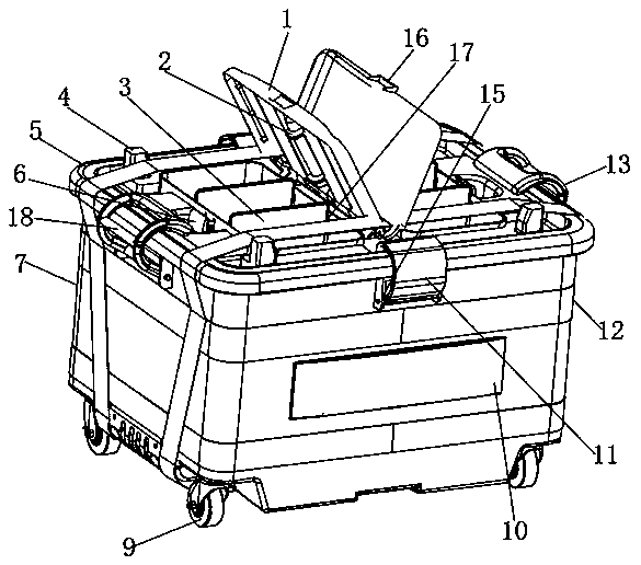
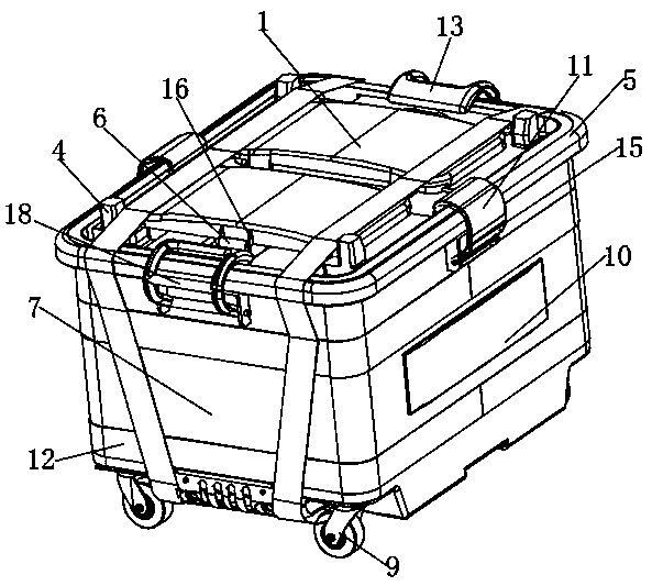
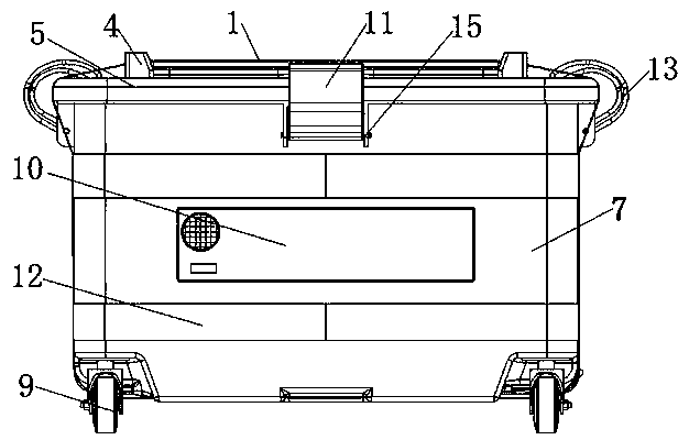
[0037] Such as Figure 1 to Figure 9 As shown, according to the preferred embodiment of the present invention, the special equipment box for the emergency department includes a lower box main body 7, and the two sides of the outer wall of the lower box main body 7 are respectively wound with external remote marching straps 12, and the bottom end of the lower box main body 7 is equipped with Universal pulley 9, and one side o...


PUM


Abstract

The invention discloses an equipment box special for an emergency department. The equipment box comprises a lower box body, external long-distance marching tightening belts are wound on the two sidesof the outer wall of the lower box body correspondingly, a box body pull rod is installed on one side of the bottom end of the lower box body, the bottom end, close to the box body pull rod, of the lower box body is hinged to a bottom box, a soft stretcher made from carbon fiber cloth is arranged at the top end of the bottom box, first rotating plates are hinged to the two sides of the bottom box,one sides of the first rotating plates are hinged to second rotating plates, the sides, away from the first rotating plates, of the second rotating plates are hinged to locking plates, perforation blocks are welded to the top ends of the locking plates, reset lock blocks are installed on the sides, close to the bottom box, of the locking plates, single-purpose locking buckles and double-purpose locking buckles are all symmetrically installed on the edge of an upper box cover, box body superposition bosses are installed at the corners of the surface of the upper box cover correspondingly, boxbody superposition grooves are formed in the positions, corresponding to universal pulleys, of the bottom end of the lower box body, and the box body superposition bosses and the box body superposition grooves form an embedded structure.

Description

technical field [0001] The invention relates to the field of emergency equipment, in particular to a special equipment box for the emergency department. Background technique [0002] In response to the rectification of the national department, the fire department was changed to the emergency department, and the equipment toolbox required by the emergency department was developed. The traditional special equipment box for the emergency department has the following deficiencies: [0003] 1. The box body does not have a strong superimposed structure, and it is inconvenient to stack the special equipment boxes of the emergency department, resulting in low utilization of transportation space. In addition, during long-distance transportation, manpower is required to reinforce the box body, which is laborious. [0004] 2. The lid of the box does not have the function of loading items, and it is easy to confuse emergency items with personal items in the box, which greatly reduces t...

Claims


Application Information

Patent Timeline
Patent Type & Authority Applications(China)
IPC IPC(8): B25H3/02
CPCB25H3/022
Inventor 梁军孙曙光
Owner 常州润邦模塑科技有限公司
Why Eureka
Try Eureka