
Tire apex turning device
A technology of apex rubber and flaps, which is applied in the field of tire production equipment, can solve problems such as poor process stability and complexity, and achieve the effects of high degree of automation, fast shaping speed, and precise stop position
- Summary
- Abstract
- Description
- Claims
- Application Information
AI Technical Summary
Problems solved by technology
Method used
Image

Examples
Embodiment Construction
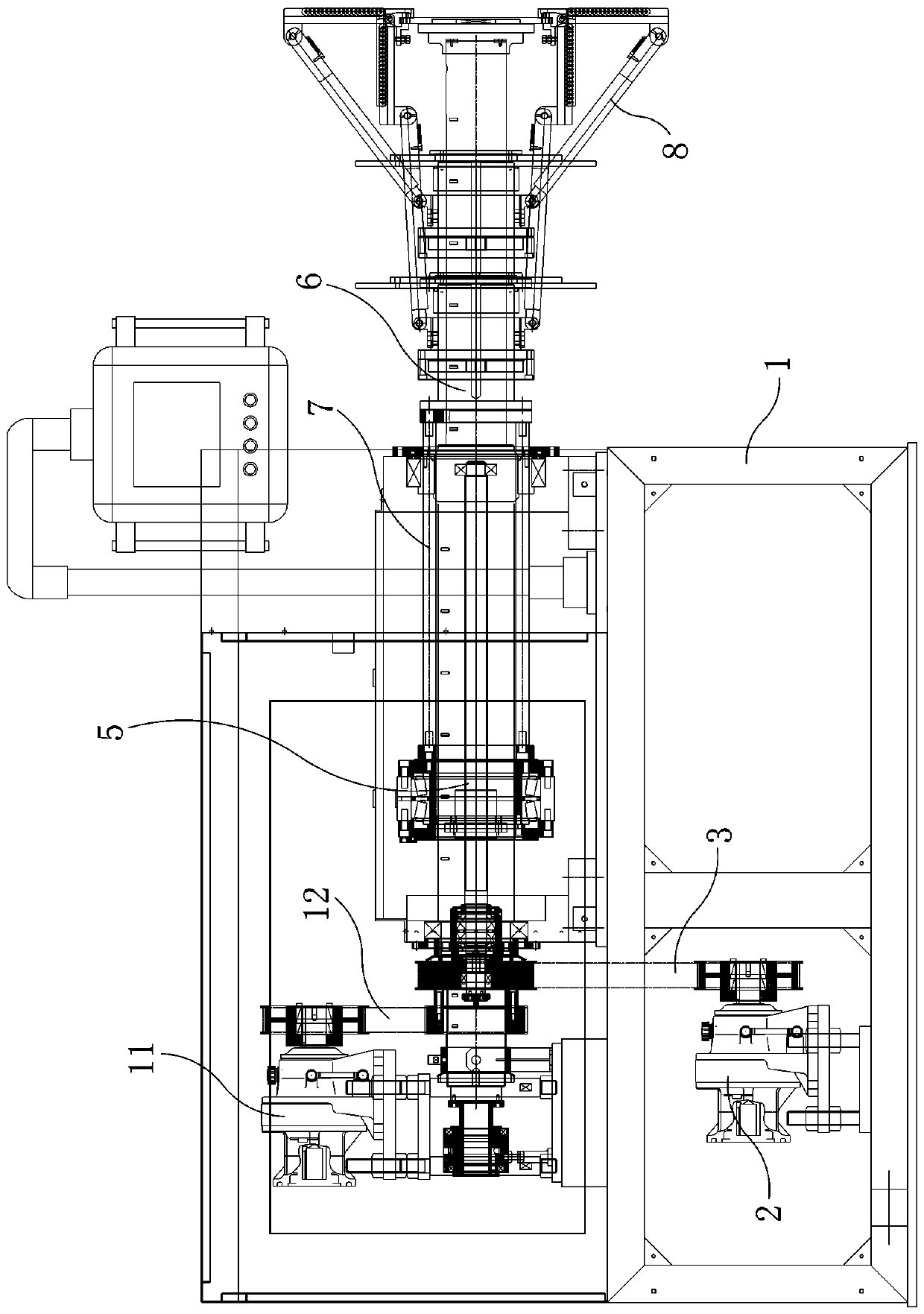
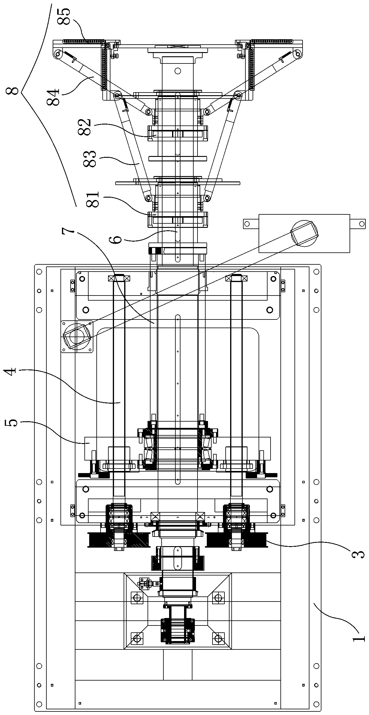
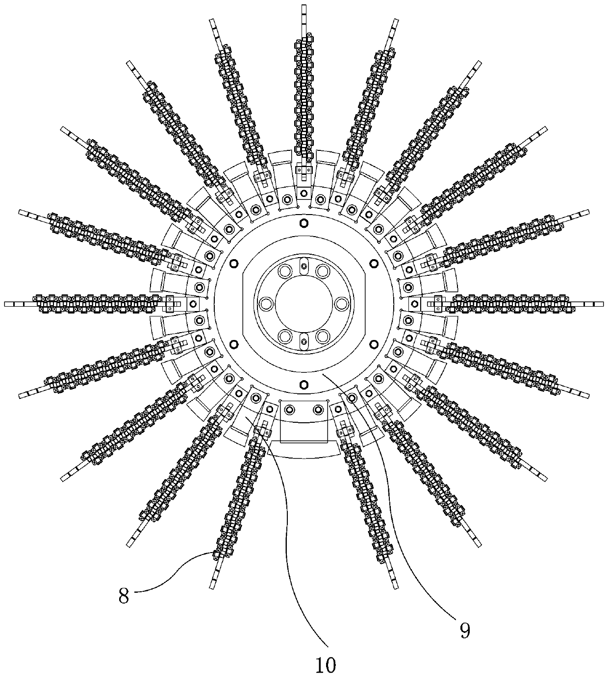
[0012] Such as Figure 1-Figure 3 As shown, the present invention is a tire apex turning device, and the apex molding drum includes a molding frame 1, a molding motor 2, a molding pulley mechanism 3, a molding screw 4, a screw seat 5, and a molding spindle 6. Push rod 7, forming link mechanism 8, suction cup seat 9, multiple suction cups 10, main shaft rotating motor 11, main shaft pulley mechanism 12.
[0013] The forming motor 2 is installed on the forming frame 1, the output shaft of the forming motor 2 is connected with one end of the forming screw 4 through the forming pulley mechanism 3, and the forming screw 4 is rotatably installed on the forming frame 1, forming The middle part of the screw mandrel 4 is screwed on the screw mandrel seat 5, and the middle part of the screw mandrel seat 5 is movably socketed on the forming main shaft 6 and can move back and forth along the forming main shaft 6. One end of the push rod 7 is fixed on the screw mandrel seat 5, and The oth...
PUM
 Abstract
Description
Claims
Application Information