floating connector

A connector, floating technology, used in the field of floating connectors, which can solve problems such as low strength

Active Publication Date: 2020-12-29
MOLEX INC
View PDF10 Cites 0 Cited by
  • Summary
  • Abstract
  • Description
  • Claims
  • Application Information

AI Technical Summary

Problems solved by technology

[0005] However, although the excessive load due to the positional deviation is suppressed, since the positional deviation is restricted between the housings, there are problems such as low strength due to the material, and there is a problem that the positional deviation cannot be stably restricted with sufficient strength. question

Method used


Image

  • floating connector
  • floating connector
  • floating connector

Examples


no. 1 example

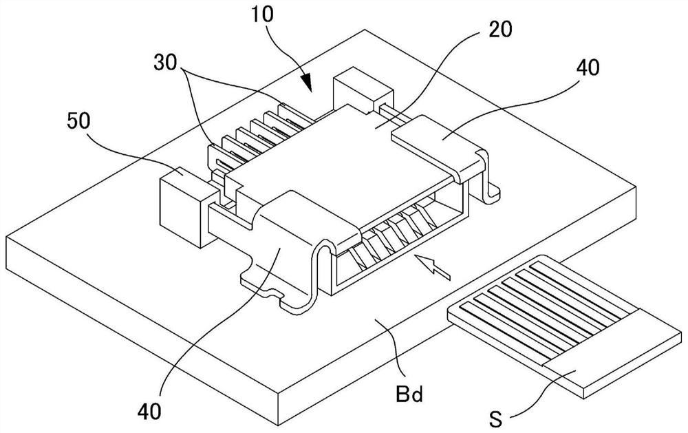
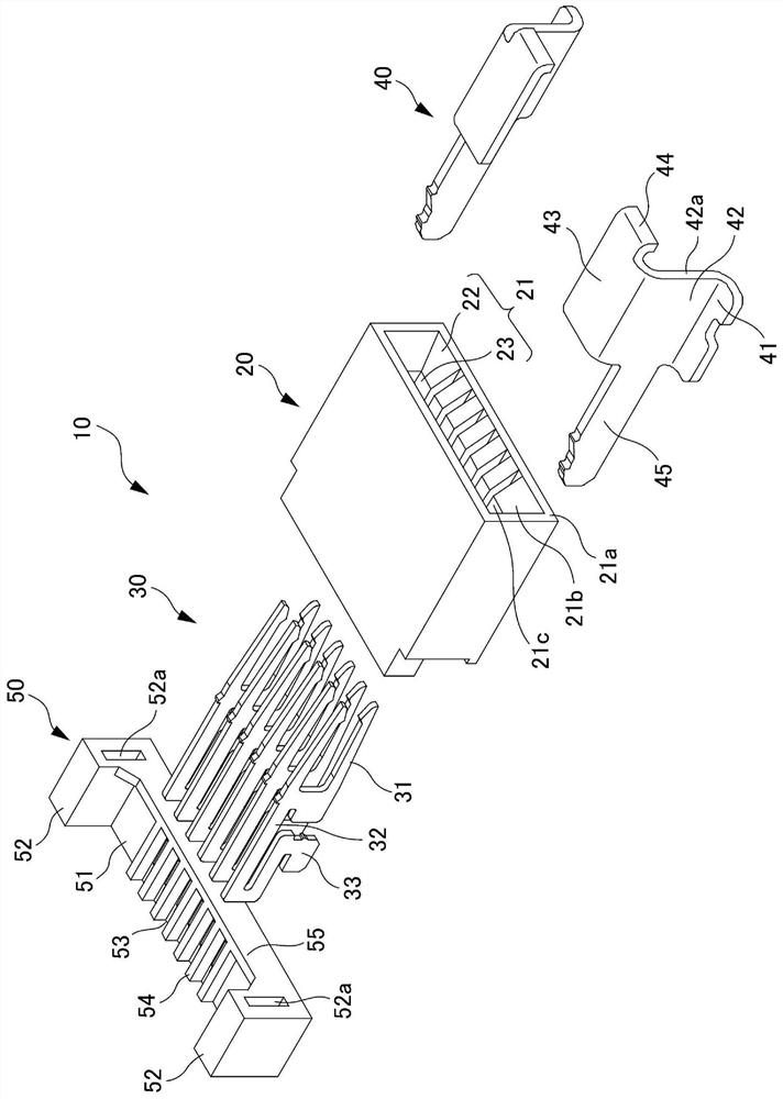
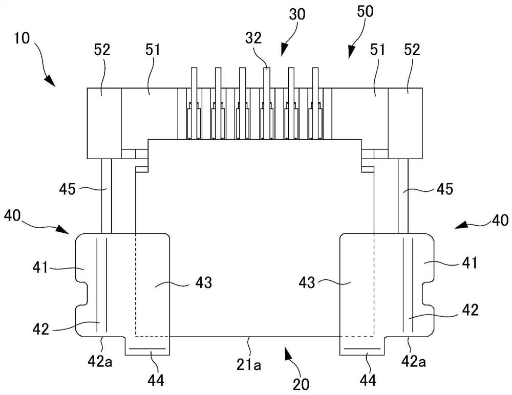
[0036] The following will refer to Figure 1 to Figure 7 The floating connector 10 according to the first embodiment is explained. like figure 1 As shown, the floating connector 10 according to the first embodiment is provided with: a box-type housing 20; a plurality of floating terminals 30 disposed inside the housing 20; a pair of substrate fixing components 40 disposed on the housing 20 and the floating terminal fixing part 50, which is fixed on the floating terminal 30 and the substrate fixing part 40 at the rear of the housing 20. A connection object S such as a board, a wire, or a board connector is embedded from the front side of the housing 20 parallel to the board Bd (direction of the white frame arrow in the drawing).

[0037] refer to figure 2 , image 3 , Figure 4 and Figure 7 Each part will be described. Inside the housing 20 is formed a housing insertion portion 21 , the housing insertion portion 21 forms an insertion opening 22 for the connection objec...

no. 2 example

[0057] Refer below Figure 8 to Figure 1 1 illustrates a floating connector 110 according to a second embodiment. like Figure 8 As shown, the floating connector 110 according to the second embodiment is provided with: a housing 120 with a front flip-type actuator 124a; a floating terminal 130 disposed inside the housing 120; a pair of substrate fixing parts 140, and the floating terminal fixing part 150 is fixed on the floating terminal 130 and the substrate fixing part behind the housing 120 . A connection object S such as a board, a wire, or a board connector is embedded from the front side of the housing 120 parallel to the board Bd (the direction of the white frame arrow in the figure).

[0058] Inside the housing 120 is a housing inserting portion 121 , and the housing inserting portion 121 forms an inserting opening 122 for inserting the connecting object S and a receiving space 123 behind the inserting opening 122 for receiving the connecting object S. The shell ins...


PUM


Abstract

The present invention provides a floating connector (10) for limiting positional deviation, which is simple in construction and has sufficient strength, and includes: a housing (20) having an embeddedopening (22) into which the connection object (S) is embedded and a housing embedded portion (21) formed by a housing space (23) housing a connection object (S); a floating terminal (30) having a base end portion (33) fixed to a substrate (Bd), a contact portion (31) contacting a connection target (S) and an elastic portion (32) between the base end portion (33) and the contact portion (31); anda substrate fixing member (40) having a substrate contact portion (41) fixed to the substrate (Bd) at the bottom surface and a side restriction portion (42) for restricting lateral movement of the housing (20) with a fixed gap (C1) on the left and right sides of the embedded opening (22). The substrate fixing member is integrally formed of metal, and the position of the embedded opening (22) and the position of the side restriction portion (42) are at least partially overlapped when viewed from the left and right sides of the floating connector (10).

Description

technical field [0001] The invention relates to a floating connector. Background technique [0002] In the prior art, there is known a floating connector equipped with a mechanism (floating mechanism) for absorbing errors and deviations in the vertical and horizontal directions that occurs when the connector is mounted on a board (for example, see Patent Document 1) . By using the floating connector, it is possible to absorb errors and deviations and prevent damage to the board itself. [0003] Patent Document 1 discloses a floating connector (referred to as a "cover connector" in Patent Document 1) that is a right-angle structure, by providing a so-called reinforcing metal piece (the reinforcing metal piece A housing and a second housing on the upper side are combined) and the left and right sides are fixed to the base plate) and a floating mechanism is added. The reinforcement metal piece is integrally attached to the side end portion of the first case, and a pair of pr...

Claims


Application Information

Patent Timeline
Patent Type & Authority Patents(China)
IPC IPC(8): H01R12/91
CPCH01R12/91
Inventor 山根哲矢
Owner MOLEX INC
Why Eureka
Try Eureka