Double-port self-excitation double-direct-current output switched reluctance generator converter system

A switched reluctance and dual DC technology, which is applied in the direction of controlling the generator through the change of the magnetic field, controlling the generator, and controlling the system, etc., can solve the problems that the voltage cannot meet the requirements, affect the excitation ability, and the influence of the self-excited power supply, etc., to reduce the filtering burden, increase power generation width, and reduce the effect of the conversion link

Active Publication Date: 2019-07-12
CHINA JILIANG UNIV
View PDF5 Cites 1 Cited by
  • Summary
  • Abstract
  • Description
  • Claims
  • Application Information

AI Technical Summary

Problems solved by technology

[0003] In many application fields of switched reluctance generators, the DC power directly sent out in the traditional sense often cannot meet the requirements, especially when it involves grid connection, several stages of boosting are required to meet the requirements; and, in some fields, different loads Different power supplies are required, especially DC power supplies with different voltages, which also need to be generated by special shunts
[0004] As a switched reluctance generator, it is a development trend to choose the self-excitation mode as the excitation method, which reduces a lot of manual maintenance workload. However, when the external mechanical power is unstable, the self-excitation power supply will also be affected, which will affect its excitation capability. , even had to shut down

Method used


Image

  • Double-port self-excitation double-direct-current output switched reluctance generator converter system
  • Double-port self-excitation double-direct-current output switched reluctance generator converter system

Examples


Embodiment Construction

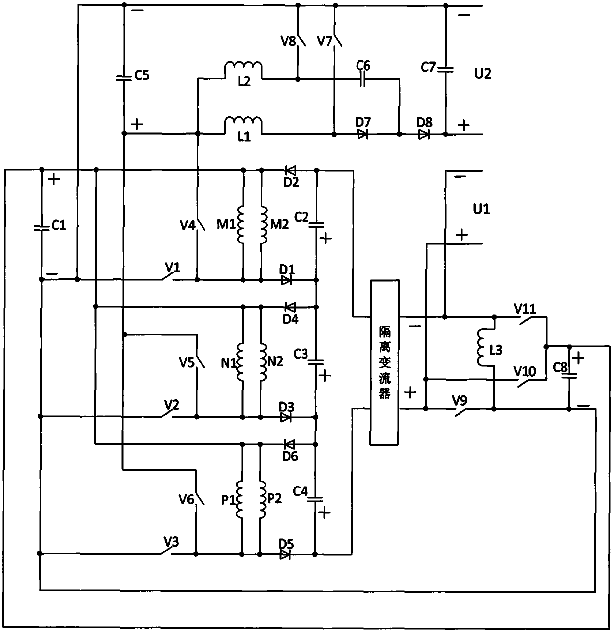
[0026] The structure diagram of the switched reluctance generator converter system with dual-port self-excitation and dual-DC output in this embodiment is shown in the attached figure 1As shown, it consists of the first capacitor C1, the second capacitor C2, the third capacitor C3, the fourth capacitor C4, the fifth capacitor C5, the sixth capacitor C6, the seventh capacitor C7, the eighth capacitor C8, the first switching tube V1 , the second switching tube V2, the third switching tube V3, the fourth switching tube V4, the fifth switching tube V5, the sixth switching tube V6, the seventh switching tube V7, the eighth switching tube V8, the ninth switching tube V9, the Tenth switching tube V10, eleventh switching tube V11, first phase winding M, second phase winding N, third phase winding P, first diode D1, second diode D2, third diode D3 , the fourth diode D4, the fifth diode D5, the sixth diode D6, the seventh diode D7, the eighth diode D8, the first inductor L1, the second ...


PUM


Abstract

The invention relates to a double-port self-excitation double-direct-current output switched reluctance generator converter system. The system comprises eight capacitors, eleven switching tubes, three-phase windings, eight diodes, three inductors and an isolation converter, wherein two paths of output are output through a double-generation loop at the generation stage of each phase winding, and when power is insufficient, a low-voltage output side and an excitation power supply are ensured preferentially, and the sacrifice of a high-voltage output side changes the wider operation range of thesystem. The power generation benefit is improved based on the strengthening of the excitation and broadening of the excitation range, and the dual-path excitation can be achieve by employing a simplestructure and through control. Besides, the staggered high-frequency switch control is employed, the electric energy quality at the high-voltage side is high, the isolation converter achieves isolation and improves the electric energy quality of the low-voltage side; and moreover, the whole system is simple in structure, convenient to regulate and control, various in function, high in adaptabilityand high in power generation benefit, and has a certain application value in the direct current user system in various power generation system fields.

Description

technical field [0001] The invention relates to the field of switched reluctance generator systems, in particular to a switched reluctance generator converter with dual-port high and low voltage adjustable excitation, high and low voltage dual output direct current and a control method thereof. Background technique [0002] The switched reluctance motor has simple structure, low cost, no winding on the rotor, and low heat dissipation pressure. As a generator, it has considerable application value. [0003] In many application fields of switched reluctance generators, the DC power directly sent out in the traditional sense often cannot meet the requirements, especially when it involves grid connection, several stages of boosting are required to meet the requirements; and, in some fields, different loads The required power sources are different, especially DC power sources of different voltages, which also need to be generated through special shunts. [0004] As a switched re...

Claims


Application Information

Patent Timeline
Patent Type & Authority Applications(China)
IPC IPC(8): H02P9/00H02P9/30H02P9/38
CPCH02P9/00H02P9/30H02P9/38
Inventor 孙冠群
Owner CHINA JILIANG UNIV
Why Eureka
Try Eureka