
Thin-wall deep-cavity piece machining jig

A technology of deep cavity and thin wall, which is applied in the field of processing jigs for thin-walled deep cavity parts. The effect of thermal deformation

Inactive Publication Date: 2019-07-16
HEYUAN POLYTECHNIC
View PDF8 Cites 0 Cited by
  • Summary
  • Abstract
  • Description
  • Claims
  • Application Information

AI Technical Summary

Problems solved by technology

Due to the unreasonable design of the jigs in the prior art, it is difficult to firmly clamp the jigs of the thin-walled deep cavity parts, which is not conducive to ensuring the processing quality of the thin-walled deep cavity parts

Method used


Image

  • Thin-wall deep-cavity piece machining jig
  • Thin-wall deep-cavity piece machining jig
  • Thin-wall deep-cavity piece machining jig

Examples


Embodiment Construction

[0036] In order to make the object, technical solution and advantages of the present invention more clear and definite, the present invention will be further described in detail below with reference to the accompanying drawings and examples. It should be understood that the specific embodiments described here are only used to explain the present invention, not to limit the present invention.

[0037] In the description of the present invention, it should be understood that the orientation or positional relationship indicated by the terms "center", "upper", "lower", "front", "rear", "left", "right" etc. are based on The orientations or positional relationships shown in the drawings are only for the convenience of describing the present invention and simplifying the description, and do not indicate or imply that the referred devices or components must have a specific orientation, be constructed and operated in a specific orientation, and therefore cannot be understood as Limitat...


PUM


Abstract

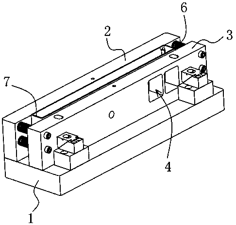
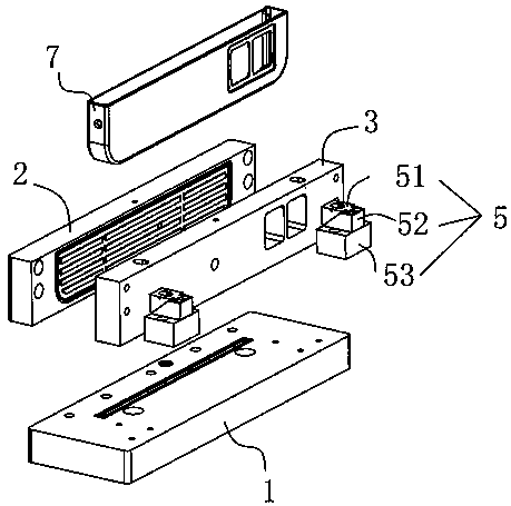
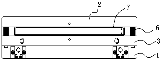
The invention provides a thin-wall deep-cavity piece machining jig. The jig comprises a base, a fixed side plate and a movable side plate, wherein the fixed side plate is fixedly arranged on the base,the movable side plate is movably arranged on the base, a clamping interval used for clamping a workpiece is formed between the fixed side plate and the movable side plate, the base and / or the fixedside plate and / or the movable side plate are provided with air grooves, and the air grooves communicates with the clamping interval. On one hand, the workpiece is clamped by the fixed side plate and the movable side plate, so that the contact area between the workpiece and the fixed side plate and between the workpiece and the movable side plate is large, the pressure applied on the workpiece during the clamping process is reduced, and the workpiece is prevented from being clamped; on the other hand, the side walls of the workpiece are sucked through the air suction mode through the air grooves, so that the product is not deformed and a knife is smoothly connected; and meanwhile, the gas provided by an air pump can be used for cooling the workpiece, so that the workpiece can be effectivelyprevented from being deformed by heating.

Description

technical field [0001] The invention relates to the technical field of mechanical processing equipment, in particular to a jig for processing thin-walled deep cavity parts. Background technique [0002] Thin-walled deep-cavity parts refer to workpieces with side walls and cavities formed in the side walls. Thin-walled deep cavity parts have been widely used in various industrial fields due to their advantages of light weight, material saving and compact structure. However, due to the poor rigidity and weak strength of thin-walled deep cavity parts, a little carelessness will cause errors, and it is difficult to guarantee the processing quality. [0003] Before manufacturing thin-walled deep-cavity parts, it is necessary to fix the workpiece with a jig, and then process the inside of the workpiece with a CNC milling machine or a machining center to obtain thin-walled deep-cavity parts with deep cavities. If a good clamping effect cannot be provided and it is difficult to fi...

Claims


Application Information

Patent Timeline
IPC IPC(8): B23Q3/08B23Q11/10
CPCB23Q3/088B23Q11/10
Inventor 刘俊英李友梁国栋林浩波梁丰袁河链梁岚吴永锦叶增良刘日春吕辉
Owner HEYUAN POLYTECHNIC
Learn More