Lifting oil cylinder with buffer structure

A lifting cylinder and cushioning structure technology, applied in the direction of lifting devices, fluid pressure actuating devices, etc., can solve the problems of large oil inlet resistance, slow lifting response, and rising oil temperature of the hydraulic system, so as to avoid oil temperature rising , Simple and reliable structure, adjustable cushioning effect

Pending Publication Date: 2019-07-16
ANHUI HELI CO LTD
View PDF0 Cites 2 Cited by
  • Summary
  • Abstract
  • Description
  • Claims
  • Application Information

AI Technical Summary

Problems solved by technology

At present, the lifting cylinder of domestic forklifts has a buffer function, but there are also problems such as unsatisfactory buffer effect, complex buffer structure, many parts, easy damage, and large oil inlet resistance; the diameter of the oil inlet at the bottom of the cylinder is generally φ15mm. Buffering, changing the direction and diameter of the oil inlet, the diameter becomes smaller to φ2~φ5mm, and the large oil inlet changes to a small oil inlet. The oil inlet is not smooth enough, the lifting response is slow, the pressure loss is large, and the oil in the hydraulic system Temperature rise and other phenomena, the present invention can solve the above-mentioned existing problems

Method used


Image

  • Lifting oil cylinder with buffer structure
  • Lifting oil cylinder with buffer structure
  • Lifting oil cylinder with buffer structure

Examples


Embodiment Construction

[0037] The present invention will be further described through the embodiments below in conjunction with the accompanying drawings.

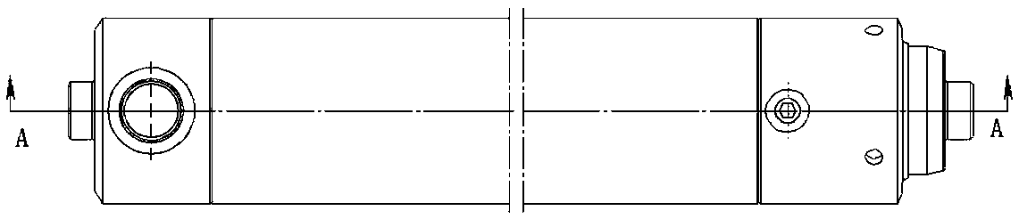
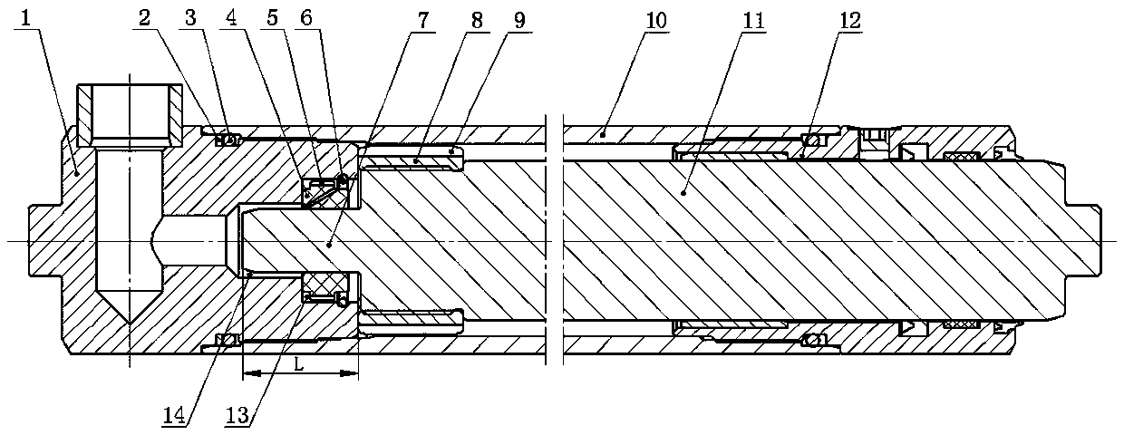
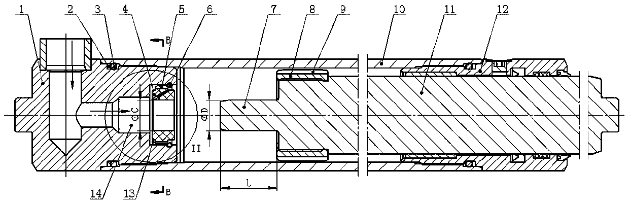
[0038] see figure 1 with figure 2 , a lifting cylinder with a buffer structure includes a cylinder 10, a cylinder bottom 1, a cylinder head 12, a plunger rod 11, and a plunger 8. The inner diameter of the cylinder 10 is 50 mm. The cylinder bottom 1 and the cylinder head 12 are respectively fixedly mounted on both axial ends of the cylinder barrel 10 . The plunger rod 11 is located in the cylinder barrel 10 , one end extends out of the cylinder head 12 , and the other end corresponds to the cylinder bottom 1 ; the plunger 8 is sleeved on one end of the plunger rod 11 in the cylinder barrel 10 . One end of the cylinder bottom 1 located in the cylinder 10 is provided with a coaxial central oil passage, one side of the cylinder bottom 1 is provided with a radial oil passage, the radial oil passage communicates with the central oil passage, and ...


PUM


Abstract

The invention relates to a lifting oil cylinder with a buffer structure. The lifting oil cylinder comprises a cylinder barrel, a cylinder bottom, a cylinder cover, a plunger rod and a plunger. According to the improvement, a three-stage step hole serves as a center oil hole of the cylinder bottom and comprises a buffer sleeve hole, a buffer column hole and a center oil hole which are communicatedin sequence; a buffer sleeve is arranged in the buffer sleeve hole, and an oil return hole is formed in the buffer sleeve; an outwards-protruding buffer column is arranged at the rod end of the plunger rod, and the buffer column and an inner hole of the buffer sleeve are in movable fit; four or more plunger grooves are formed in the outer circumference of the plunger; and when a buffer function isachieved during work, the plunger rod moves towards one side of the cylinder bottom, the buffer column gradually stretches into the buffer column hole through the buffer sleeve, a small gap is formedbetween the cylindrical face of the buffer column and the inner hole of the buffer sleeve, most oil flows back to an oil tank through the oil return hole in the buffer sleeve, and buffer is formed. During work, when entering oil ascends, part of hydraulic oil directly acts on the bottom of the buffer column, part of hydraulic oil enters the cylinder barrel through 6 oil grooves around the buffersleeve, ascending fast responding is achieved, pressure losses are small, and oil temperature is prevented from being increased.

Description

technical field [0001] The invention belongs to the technical field of forklifts, and in particular relates to a lifting cylinder of a forklift. Background technique [0002] As an important engineering vehicle, forklifts are widely used in various industries to stack goods; the lifting cylinder is used as a hydraulic actuator, see Figure 13 , plays a very important role in ensuring the smooth operation of the mast. At present, the lifting cylinder of domestic forklifts has a buffer function, but there are also problems such as unsatisfactory buffer effect, complex buffer structure, many parts, easy damage, and large oil inlet resistance; the diameter of the oil inlet at the bottom of the cylinder is generally φ15mm. Buffering, changing the direction and diameter of the oil inlet, the diameter becomes smaller to φ2~φ5mm, and the large oil inlet changes to a small oil inlet. The oil inlet is not smooth enough, the lifting response is slow, the pressure loss is large, and th...

Claims


Application Information

Patent Timeline
Patent Type & Authority Applications(China)
IPC IPC(8): F15B15/14F15B15/22B66F9/22
CPCB66F9/22F15B15/1428F15B15/1447F15B15/226
Inventor 王冬艳王茂兵徐玲灿胡晓海
Owner ANHUI HELI CO LTD
Why Eureka
Try Eureka