Joint surface stiffness test bench and using method thereof

A technology that combines surfaces and test benches, and is applied in the testing, measuring devices, instruments, etc. of machine/structural components to achieve the effect of wide application, easy replacement and maintenance, and realization of changes.

Active Publication Date: 2019-07-16
济南高投能源发展有限公司
View PDF16 Cites 2 Cited by
  • Summary
  • Abstract
  • Description
  • Claims
  • Application Information

AI Technical Summary

Problems solved by technology

[0003] The distance between the pressure detection part and the part to be tested can only be adjusted in a small range by turning the screw rod in the existing joint surface stiffness test bench. Therefore, when measuring parts of different sizes, the existing test bench has a large limitations of use

Method used


Image

  • Joint surface stiffness test bench and using method thereof
  • Joint surface stiffness test bench and using method thereof
  • Joint surface stiffness test bench and using method thereof

Examples


Embodiment Construction

[0023] In order to clearly illustrate the technical features of the solution, the solution will be described below through specific implementation modes.

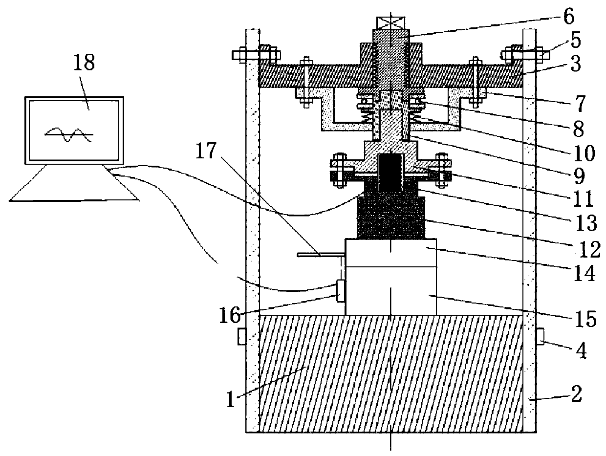
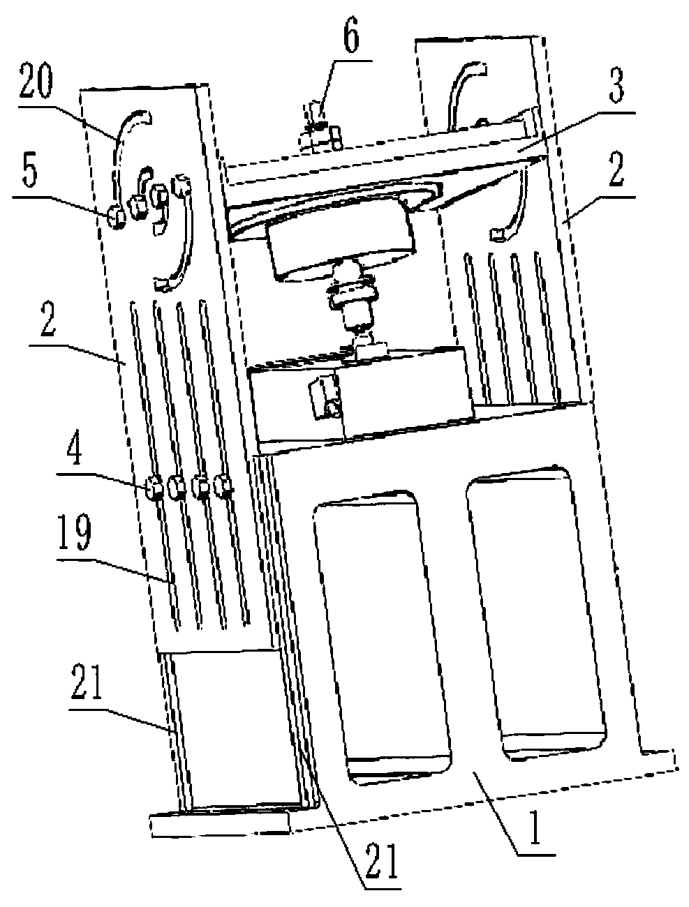
[0024] A joint surface stiffness test bench, such as figure 1 , 2 , 3, including the base 1, the part II15 placed on the base 1, the part I14 placed on the part II15, the laser displacement sensor 16 is installed on the part II15, the reflector 17 is installed on the part I14, and the laser displacement sensor 16 The emitted laser light acts on the reflection plate 17 . A side plate 2 is respectively connected to two opposite side walls of the base 1, and each side plate 2 is provided with at least one long hole 19 along its length direction, and the fastening bolts 4 correspondingly pass through each long hole. 19 and be connected with the positioning screw holes provided on the base 1. An upper cover 3 is connected between the two side plates 2 above the base 1, and a pressure detection mechanism is connected on the up...


PUM


Abstract

The invention relates to a joint surface stiffness test bench and a using method thereof. The joint surface stiffness test bench comprises a base, a part II placed on the base, and a part I placed onthe part II; a laser displacement sensor is mounted on the part II, a reflector is mounted on the part I, and a side plate is separately connected to the opposite side walls of the base; at least oneelongated hole is arranged on each side plate along the length direction; and fastening bolts correspondingly passes through each of the elongated holes and is connected to positioning screw holes provided on the base. The distance between a pressure detecting mechanism and a part to be tested can be flexibly adjusted in a wide range; therefore, the joint surface stiffness test bench is not limited by the size of the parts during use, and has a wide application range.

Description

technical field [0001] The invention relates to the technical field of detection instruments, in particular to a joint surface stiffness test bench and a method for using the same. Background technique [0002] There are a large number of joint surfaces in complex mechanical systems such as machine tools, gas turbines, and automobile engines, which destroy the continuity of the mechanical system structure and affect the overall performance of the mechanical system to a large extent. The connection characteristics of the joint surface present a certain degree of nonlinearity, and introducing the characteristic parameter model of the joint surface into the modeling process of the whole system can effectively improve the performance prediction ability of the whole machine in the product design stage. [0003] The distance between the pressure detection part and the part to be tested can only be adjusted in a small range by rotating the screw rod in the existing joint surface st...

Claims


Application Information

Patent Timeline
Patent Type & Authority Applications(China)
IPC IPC(8): G01M99/00
CPCG01M99/005
Inventor 卢世坤高迟王明
Owner 济南高投能源发展有限公司
Why Eureka
Try Eureka