Carotid coils for MRI systems

A magnetic resonance and carotid artery technology, applied in the field of carotid artery coils, can solve problems that affect diagnostic accuracy, inconvenient positioning, and insufficient resolution of the carotid artery.

Active Publication Date: 2021-07-06
深圳市凯利鹏达医疗科技有限公司
View PDF0 Cites 0 Cited by
  • Summary
  • Abstract
  • Description
  • Claims
  • Application Information

AI Technical Summary

Problems solved by technology

The bifurcation of the carotid artery is just below the lower jaw of the human body, which brings inconvenience to the positioning of the carotid artery MRI.
Early carotid magnetic resonance angiography uses neck coil imaging. Since the neck coil is not a dedicated carotid magnetic resonance angiography coil, sufficient resolution cannot be obtained in the carotid artery, which affects the accuracy of diagnosis.
[0005] Most of the carotid magnetic resonance angiography coils currently on the market are wrapped around the neck with strip-shaped coils. Although the imaging effect has been greatly improved, the center of the coil imaging in this way is the common carotid artery area, which is difficult to pass through. Imaging to diagnose blood vessels near the carotid bifurcation close to the skin surface

Method used


Image

  • Carotid coils for MRI systems
  • Carotid coils for MRI systems
  • Carotid coils for MRI systems

Examples


Embodiment Construction

[0029] The specific implementations and examples of the present invention will be described in detail below in conjunction with the accompanying drawings. The described specific examples are only used to explain the present invention, and are not intended to limit the specific implementations of the present invention.

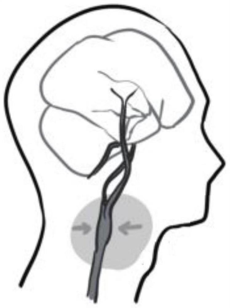
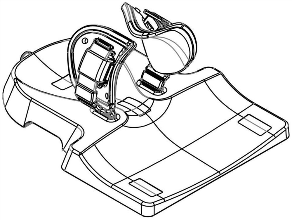
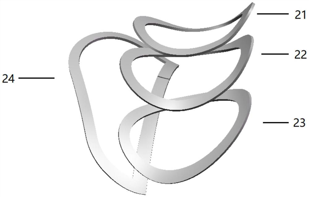
[0030] A carotid artery coil used in a magnetic resonance system of the present invention includes a left signal collecting device and a right signal collecting device connected to a base, and the left signal collecting device and the right signal collecting device respectively include The receiving unit CH1, the receiving unit CH2 and the receiving unit CH3 arranged in sequence, and a receiving unit CH4 superimposed on the receiving unit CH1, the receiving unit CH2 and the receiving unit CH3, which is located between the neck and the jaw; The magnetic resonance system inputs a control sequence signal BIAS to the receiving unit CH1, CH2, CH3, and CH4; the receiv...


PUM


Abstract

The present invention relates to a carotid artery coil for a magnetic resonance system, which includes a left signal collection device and a right signal collection device connected to a base, and further includes a receiving unit CH1, a receiving unit CH2 and a receiving unit sequentially arranged around the neck unit CH3, and a receiving unit CH4 superimposed on it, located between the neck and the jaw; the magnetic resonance system inputs a control sequence signal BIAS to each receiving unit; each receiving unit according to the control sequence signal BIAS outputs magnetic resonance signals to the magnetic resonance system. The left and right signal collection device of the present invention is wrapped around the patient's neck from the left and right sides, avoiding the feeling of suffocation caused by the coil pressing the larynx during the imaging process, taking the carotid artery bifurcation as the imaging center, with strong signal collection ability and good imaging quality. Two diodes are used in the Bias circuit, which avoids the influence of the transient effect of capacitor charging and discharging, and the switching time is short.

Description

technical field [0001] The invention relates to a carotid coil for a magnetic resonance system. Background technique [0002] Magnetic resonance system is a large-scale medical diagnostic equipment, which is widely used in modern hospitals. Magnetic resonance angiography (MR angiography, MRA) is a non-invasive angiography method that does not require intubation and contrast agents. There are currently two main technologies for MRA vascular imaging data acquisition: ① time of flight (TOF) technology, whose imaging principle is to use the special "flow effect" of MR. In the GE sequence of MRA imaging (gradient echo sequence, also commonly used as GRE as an abbreviation), the radio frequency transmitting coil saturates the static tissue protons in the active layer through the action of intermittently provided RF pulses, and the longitudinal magnetization disappears. When the inflow of blood occurs, its protons are in a non-saturated state, and the degree of longitudinal magne...

Claims


Application Information

Patent Timeline
Patent Type & Authority Patents(China)
IPC IPC(8): G01R33/34
CPCG01R33/34046
Inventor 古文海
Owner 深圳市凯利鹏达医疗科技有限公司
Why Eureka
Try Eureka