
Musical instrument bracket

A musical instrument and hanger technology, applied in the field of musical instrument brackets, can solve problems such as inability to fold, wear and damage of the left and right rocker arms, and achieve the effects of convenient use and portability, increased stability, and increased friction

Pending Publication Date: 2019-07-16
佛山安炜达金属制品有限公司
View PDF8 Cites 0 Cited by
  • Summary
  • Abstract
  • Description
  • Claims
  • Application Information

AI Technical Summary

Problems solved by technology

[0002] Musical instruments generally refer to utensils that can play timbre and rhythm in various ways. They are generally divided into national musical instruments and Western musical instruments. They can produce musical sounds and recreate musical art. Humans express and exchange thoughts and feelings by playing musical instruments. , the definition of musical instruments, the music industry and the musical instrument academic circles have different views, the music industry believes that the sounding apparatus used for music is a musical instrument; Bracket, but at present the base of the hanger bracket is clamped with a tight lock, there is a risk of failure when placing heavy objects, and it cannot be folded, so it is inconvenient to carry, and the existing brackets on the market All hangers adopt double rocker arm structure. Over time, the left and right rocker arms will wear out and malfunction. At this time, if the rocker arms are not linked to lock the hanger, the musical instrument may slip from the hanger, and the rocker The arm-type hanger will be damaged after being taken out forcibly, so it is not suitable for promotional use

Method used


Image

  • Musical instrument bracket
  • Musical instrument bracket
  • Musical instrument bracket

Examples


Embodiment Construction

[0033] The following will clearly and completely describe the technical solutions in the embodiments of the present invention with reference to the accompanying drawings in the embodiments of the present invention. Obviously, the described embodiments are only some, not all, embodiments of the present invention. Based on the embodiments of the present invention, all other embodiments obtained by persons of ordinary skill in the art without making creative efforts belong to the protection scope of the present invention.

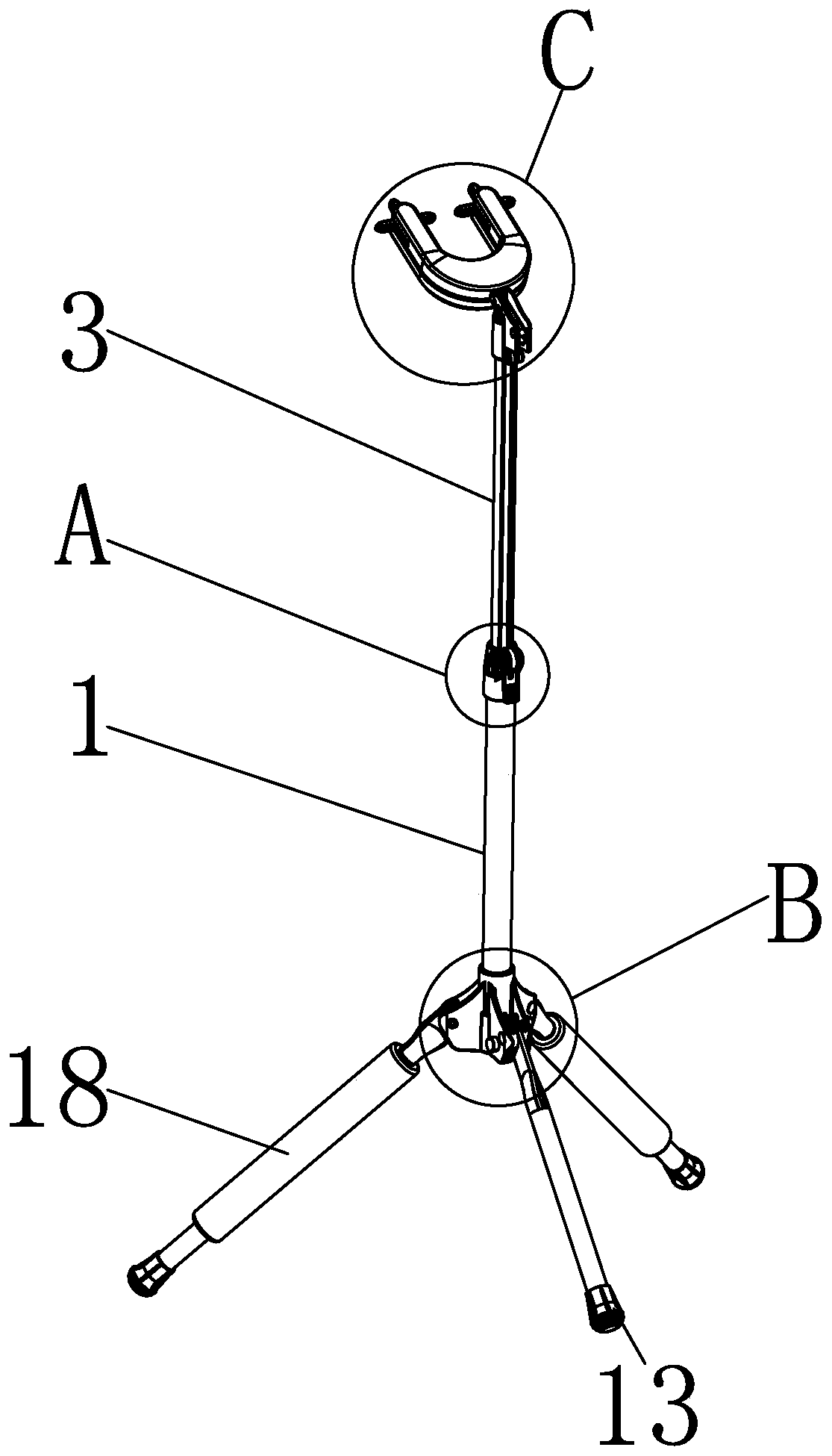
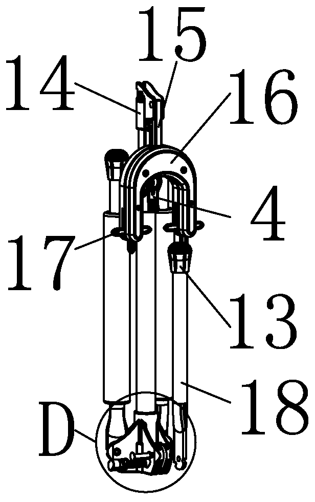
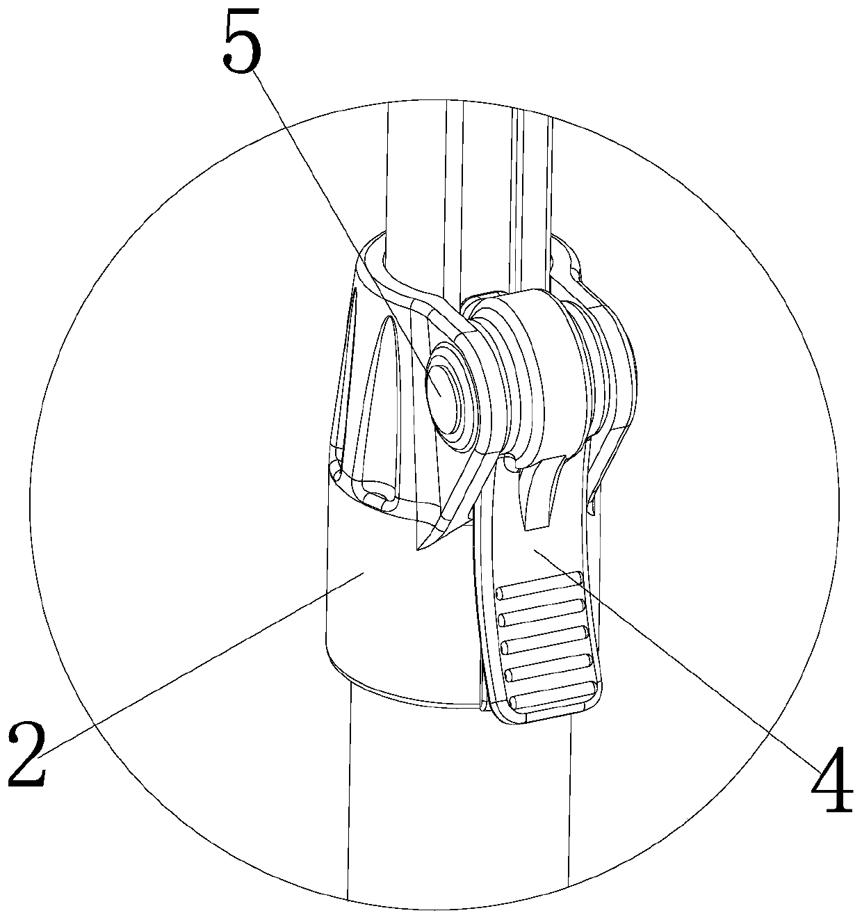
[0034] see Figure 1-10 , a musical instrument bracket, comprising a hollow tube 1, the top of the hollow tube 1 is sleeved with a limit seat 2, and the top of the limit seat 2 is sleeved with a special-shaped tube 3, through the setting of the special-shaped tube 3, it can ensure that the guitar hook is supported. The first hollow nail 5 is installed on the inner side of the limit seat 2, the surface of the first hollow nail 5 is movably connected with the ec...


PUM


Abstract

The invention discloses a musical instrument bracket, which comprises a hollow pipe. A triangular seat sleeves the bottom of the hollow pipe, and second hollow nails are mounted on the inner side of the triangular seat; foot pipes are mounted on the inner side of the triangular seat through cooperation of the second hollow nails, and concave teeth are stamped on the tops of the foot pipe; triangular seat pressing blocks are mounted on the inner side of the triangular seat, and grooves are formed in the surfaces of the triangular seat pressing blocks; and convex blocks engaged with the concaveteeth are stamped on the inner sides of the grooves, and springs are mounted on the inner sides of the triangular seat pressing blocks. Through mutual cooperation of the hollow pipe, a limiting seat,a special-shaped pipe, an eccentric pressing arm, first hollow nails, the triangular seat, the triangular seat pressing blocks, the first spring, the grooves, the convex blocks, the concave teeth, thesecond hollow nails, a mounting seat, a mounting rod, a hanging frame, first rotating wheels, the foot pipes, a face cover, a bottom cover, a connecting rod lock, second rotating wheels and the second spring, the problems that a base on an existing bracket is poor in stability, cannot be folded and thus is inconvenient to carry, and a hanging frame is prone to being damaged are solved.

Description

technical field [0001] The invention relates to the technical field of musical instrument auxiliary equipment, in particular to a musical instrument bracket. Background technique [0002] Musical instruments generally refer to utensils that can play timbre and rhythm in various ways. They are generally divided into national musical instruments and Western musical instruments. They can produce musical sounds and recreate musical art. Humans express and exchange thoughts and feelings by playing musical instruments. , the definition of musical instruments, the music industry and the musical instrument academic circles have different views, the music industry believes that the sounding apparatus used for music is a musical instrument; Bracket, but currently the base of the hanger bracket is clamped with a tight lock, there is a risk of failure when placing heavy objects, and it cannot be folded, so it is inconvenient to carry, and the existing brackets on the market All hangers...

Claims


Application Information

Patent Timeline
Patent Type & Authority Applications(China)
IPC IPC(8): G10G5/00
CPCG10G5/00
Inventor 冯健恒
Owner 佛山安炜达金属制品有限公司
Learn More