Small-target surface vertical target dispersion photoelectric measurement device

A photoelectric measurement and density technology, which is applied to targets, target indication systems, offensive equipment, etc., can solve the problem of inability to measure the density of projectiles with a caliber below 30mm, and solves the problem of unstable illumination and high safety of personnel and equipment. , the effect of simple structure

Inactive Publication Date: 2010-12-22
XIAN TECHNOLOGICAL UNIV
View PDF10 Cites 39 Cited by
  • Summary
  • Abstract
  • Description
  • Claims
  • Application Information

AI Technical Summary

Problems solved by technology

[0005] The purpose of the present invention is to aim at the technical status quo of the existing indoor vertical target concentration measurement system and device, and overcome the deficiency that the linear array CCD camera intersection measurement system cannot measure the vertical target concentration of projectiles with a caliber below 30mm indoors.

Method used


Image

  • Small-target surface vertical target dispersion photoelectric measurement device
  • Small-target surface vertical target dispersion photoelectric measurement device
  • Small-target surface vertical target dispersion photoelectric measurement device

Examples


Embodiment 1

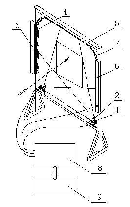
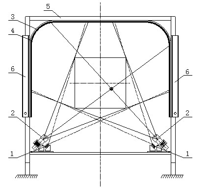
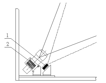
[0023] Example 1: see figure 1 , figure 2 with image 3 , a photoelectric measuring device for vertical target density on a small target surface, comprising a laser light source assembly, an original reflective film 4, a light curtain target 6, a data acquisition controller 8, a main control computer 9 and two orthogonal linear array CCD cameras 2. Said laser light source assembly is two laser light sources 1 capable of producing a fan-shaped light curtain surface. The power of the semiconductor laser light source is 70mW, which are respectively arranged on the inner side of two linear array CCD cameras 2 and the main axis is coplanar with the optical axis of the linear array CCD camera. , the emitted fan-shaped beam is coplanar with the field of view of the CCD camera. Said original reflective film 4 is strip-shaped with a width of 15 mm, which is arranged relative to the line CCD camera 2 and perpendicular to the light curtain emitted by the laser light source assembly...

Embodiment 2

[0031] Example 2: see Figure 4 . The difference with Embodiment 1 is that said laser light source assembly 1 is four laser light sources that emit fan-shaped light beams, which are respectively paired and symmetrically arranged on both sides of two line array CCD cameras 2 and the main axes are all aligned with the line array The optical axis of the CCD camera is in the same plane, and the emitted fan-shaped beam is in the same plane as the field of view of the line array CCD camera.

[0032] In this embodiment, the two laser light sources 1 are placed above and below the linear CCD camera 2 at the same time, and the main axes of the two laser light sources are in the same plane as the optical axis of the linear CCD camera. This design can improve the brightness of the field of view of the linear array CCD camera and effectively eliminate false projectile images.

Embodiment 3

[0033] Example 3: see Figure 5 . The difference with Embodiment 1 is that said laser light source assembly 1 includes two laser light sources 1 emitting fan-shaped light sources and corresponding half mirrors 7, and the main axis of laser light source 1 is perpendicular to the line array CCD camera 2 light beams. axis and the two light-emitting optical axes intersect, the half mirror 7 is placed at the intersection of the optical axis of the line array CCD camera 2 and the laser light source 1, and its reflective surface faces the laser light source and forms an angle of 45° with the laser light source optical axis.

[0034] This scheme ensures that the main axis of the laser is coaxial with the optical axis of the linear array CCD camera, and ensures that the light emitted by the projectile blocking the laser beam is in the same position as the light reflected back through the original reflective film.


PUM


Abstract

The invention relates to a small-target surface vertical target dispersion photoelectric measurement device. The traditional contact measurement method has the problems that the labor intensity is high, the measuring results are greatly influenced by manual work, and particularly repeated holes cannot be identified and the measuring results cannot be provided in real time. A laser light source assembly is arranged symmetrically on the lateral surface of a linear array CCD camera, an emergent main axis of the laser light source assembly is coplanar with a main axis of the linear array CCD camera, and an original-direction reflecting film is opposite to the linear array CCD camera and vertical to a light curtain sent by the laser light source assembly. The device adopts an integrated structural design, forms the light curtain converged relative to the CCD camera by matching the laser assembly of a small-power semiconductor laser and the low-cost original-direction reflecting film, reliably acquires the information of positions where bullets pass through the light curtain, effectively solves the problems of unstability and low sensitivity of light used indoors during a CCD convergence test, and has the advantages of convenient installation and debugging, simple structure, and high safety of personnel and equipment.

Description

technical field [0001] The invention belongs to the field of ballistic parameter testing outside the shooting range, and mainly relates to a photoelectric measuring device for measuring the landing coordinates of flying projectiles, in particular to a photoelectric measuring device for vertical target density on a small target surface. Background technique [0002] In the production and development of light weapons, the target concentration of launched projectiles is an important parameter to measure the performance of guns and ammunition, and must be measured in product inspection. The traditional contact measurement method is to erect plywood or thin wood boards at the positions specified by the ballistics according to the requirements of the test regulations, paste paper on the boards, take off the paper and measure the positions of a group of bullet holes manually to calculate the density Degree parameters such as R100, R50, R+L, etc. This type of method is labor-intens...

Claims


Application Information

Patent Timeline
Patent Type & Authority Applications(China)
IPC IPC(8): F41J5/02
Inventor 马卫红倪晋平董涛田会蔡荣立
Owner XIAN TECHNOLOGICAL UNIV
Why Eureka
Try Eureka