Device, method, storage medium, equipment and rail vehicle for long-distance hole distance measurement

A technology of measuring device and measuring method, which is applied in the direction of measuring device, neural learning method, optical device, etc., can solve the problems of complex operation, inaccurate measurement data, and measurement failure of the three-coordinate measurement method, and achieve repeatable positioning accuracy , Realize the measurement process and reduce the effect of measurement error

Active Publication Date: 2022-04-15
CRRC QINGDAO SIFANG CO LTD
View PDF11 Cites 1 Cited by
  • Summary
  • Abstract
  • Description
  • Claims
  • Application Information

AI Technical Summary

Problems solved by technology

Caliper measurement is to manually measure the specific size between two holes, and finally determine the measurement result through visual readings. At the same time, taking into account the influence of various external factors, this will definitely result in poor repeatability of the measured distance and inaccurate measurement data. And the final measurement results are saved through manual recording and uploading, which inevitably leads to mistakes and increases many uncontrollable factors
[0004] The inventor found that the three-coordinate measurement method is ideal in terms of the measurement results of the center distance between two holes, but the operation of the three-coordinate measurement method is complicated, time-consuming and laborious, and a little careless operation may cause measurement failure or even damage the measurement tool; and the caliper measurement and The three-coordinate measurement method is almost used in the measurement of the center distance of small holes in short distances, and it is difficult for both of them to measure the center distance of small holes in long distances.

Method used


Image

  • Device, method, storage medium, equipment and rail vehicle for long-distance hole distance measurement
  • Device, method, storage medium, equipment and rail vehicle for long-distance hole distance measurement
  • Device, method, storage medium, equipment and rail vehicle for long-distance hole distance measurement

Examples


Embodiment 1

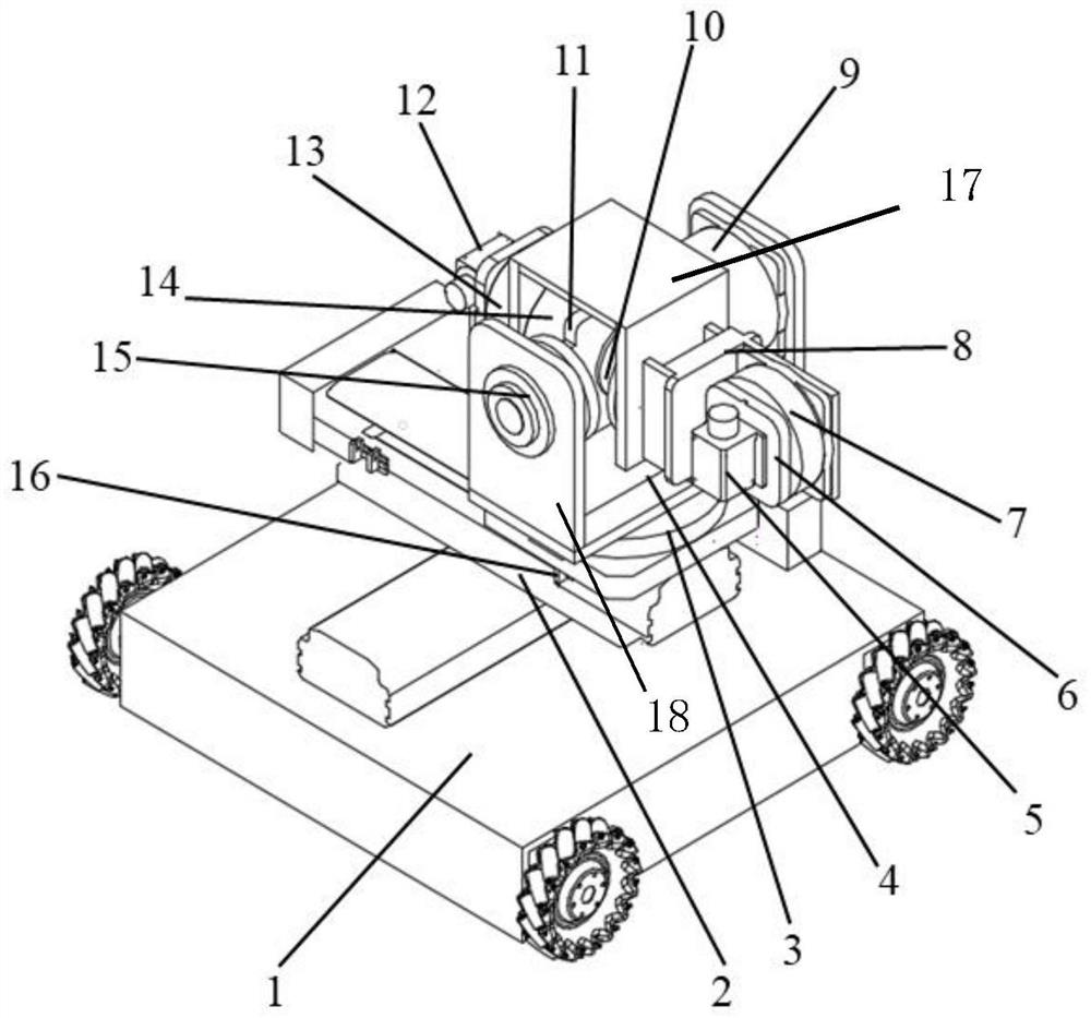
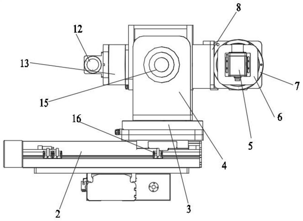
[0064] In a typical embodiment of the present invention, such as figure 1 As shown, a long-distance hole distance measurement device is proposed, which includes a moving part 1, a driving part 2 is fixedly installed on the top of the moving part 1, a first power device 3 is fixed on the top of the driving part 2, and X-Y pitch is fixed on the top of the first power device 3 The adjustment platform 4, the second power device 13 is fixedly installed on the left side of the X-Y pitch adjustment platform 4, the third power device 7 is fixedly installed on the right side of the X-Y pitch adjustment platform 4, and the image acquisition component is fixedly installed on the rotary platform driven by the third power device 7 , the laser range finder 12 is fixedly installed on the slewing platform driven by the second power unit 13 .

[0065] In this embodiment, the image acquisition component adopts a CCD industrial camera 5 .

[0066] The measuring device is equipped with a CCD ind...

Embodiment 2

[0086] This embodiment provides an operation method for measuring the hole distance using the above-mentioned long-distance hole distance measuring device, the steps of which are:

[0087] a. Move the measuring device to the front of the first hole to be measured through the moving part 1, adjust the driving part 2 through the servo motor to make the CCD industrial camera 5 be in an accurate working position, and place it on the plane of the two holes to be measured Prepare the side wall on the side to measure the vertical distance between the laser rangefinder 12 and the side wall; control the rotation of the first power unit 3 so that the upper measuring device is at a suitable angle; complete the preparatory work before the measurement;

[0088]b. Control the fifth power unit 9 and the fourth power unit 14 inside the X-Y pitch adjustment platform 4 to drive the second rotation unit 15 and the first rotation unit 10, and the third power unit 7 installed on the right side of t...

Embodiment 3

[0092] In this embodiment, a method for measuring hole distance using the long-distance hole distance measuring device as described above is proposed, comprising the following steps:

[0093] S1: Real-time acquisition of images of different long-distance interval holes;

[0094] S2: Extract the edge of the image of the hole to obtain the grayscale image, edge image and gradient image of the image;

[0095] S3: Perform feature extraction on the edge map and the gradient map to obtain the characteristic parameters of the directional gradient histogram;

[0096] S4: Train the neural network according to the characteristic parameters to obtain the target neural network;

[0097] S5: Collect multiple images of the distance-measuring hole in real time, perform feature extraction on the collected images of the distance-measuring hole according to the method of edge extraction and feature parameter extraction, and input the extracted feature data into the target neural network , to ...


PUM


Abstract

The invention discloses a long-distance hole distance measurement device, method, storage medium, equipment and rail vehicle, comprising: an image acquisition element, used to collect edge images of holes to be measured; a distance measurement element, used to measure the edge of the hole to be measured The distance from the reference object; the angle adjustment mechanism, which is connected with the image acquisition element and the distance measurement element, to drive the image acquisition element and the distance measurement element to adjust the angle; the moving part, which is connected with the angle adjustment mechanism, to drive the image acquisition element, the distance measurement element Adjust the position from the component.

Description

technical field [0001] The invention belongs to the technical field of mechatronics measurement and control, and in particular relates to a long-distance hole distance measurement device, method, storage medium, equipment and rail vehicle. Background technique [0002] The statements herein merely provide background information related to the present invention and do not necessarily constitute prior art. [0003] At present, in the field of rail transit vehicles and other processing and manufacturing, the distance between the centers of two holes is usually measured by calipers and three-coordinate measuring instruments. Caliper measurement is to manually measure the specific size between two holes, and finally determine the measurement result through visual readings. At the same time, taking into account the influence of various external factors, this will definitely result in poor repeatability of the measured distance and inaccurate measurement data. Moreover, the final ...

Claims


Application Information

Patent Timeline
Patent Type & Authority Patents(China)
IPC IPC(8): G01B11/14G06N3/08G06T7/13
CPCG01B11/14G06T7/13G06N3/08G06T2207/20081G06T2207/20084
Inventor 宁海石万帅周辉张会琪
Owner CRRC QINGDAO SIFANG CO LTD
Why Eureka
Try Eureka