Eureka AIR delivers breakthrough ideas for toughest innovation challenges, trusted by R&D personnel around the world.

Cooling device and annealing furnace

A technology of cooling device and heat preservation device, applied in sustainable manufacturing/processing, electrical components, climate sustainability, etc., can solve the problems of difficult furnace body temperature, lowering infrared lamps, and difficult to accurately control furnace body temperature, etc. The effect of improving the service life

Pending Publication Date: 2019-07-16
无锡奥特维旭睿科技有限公司
View PDF0 Cites 0 Cited by
  • Summary
  • Abstract
  • Description
  • Claims
  • Application Information

AI Technical Summary

Problems solved by technology

[0004] In order to solve the problem in the related art that it is difficult to reduce the temperature of the furnace body by reducing the power of the infrared lamp tube, and it is difficult to accurately control the temperature of the furnace body, the application provides a cooling device and an annealing furnace. The specific technical scheme is as follows:

Method used


Image

  • Cooling device and annealing furnace
  • Cooling device and annealing furnace
  • Cooling device and annealing furnace

Examples


Embodiment Construction

[0027] Reference will now be made in detail to the exemplary embodiments, examples of which are illustrated in the accompanying drawings. When the following description refers to the accompanying drawings, the same numerals in different drawings refer to the same or similar elements unless otherwise indicated. The implementations described in the following exemplary examples do not represent all implementations consistent with the present invention. Rather, they are merely examples of apparatuses and methods consistent with aspects of the invention as recited in the appended claims.

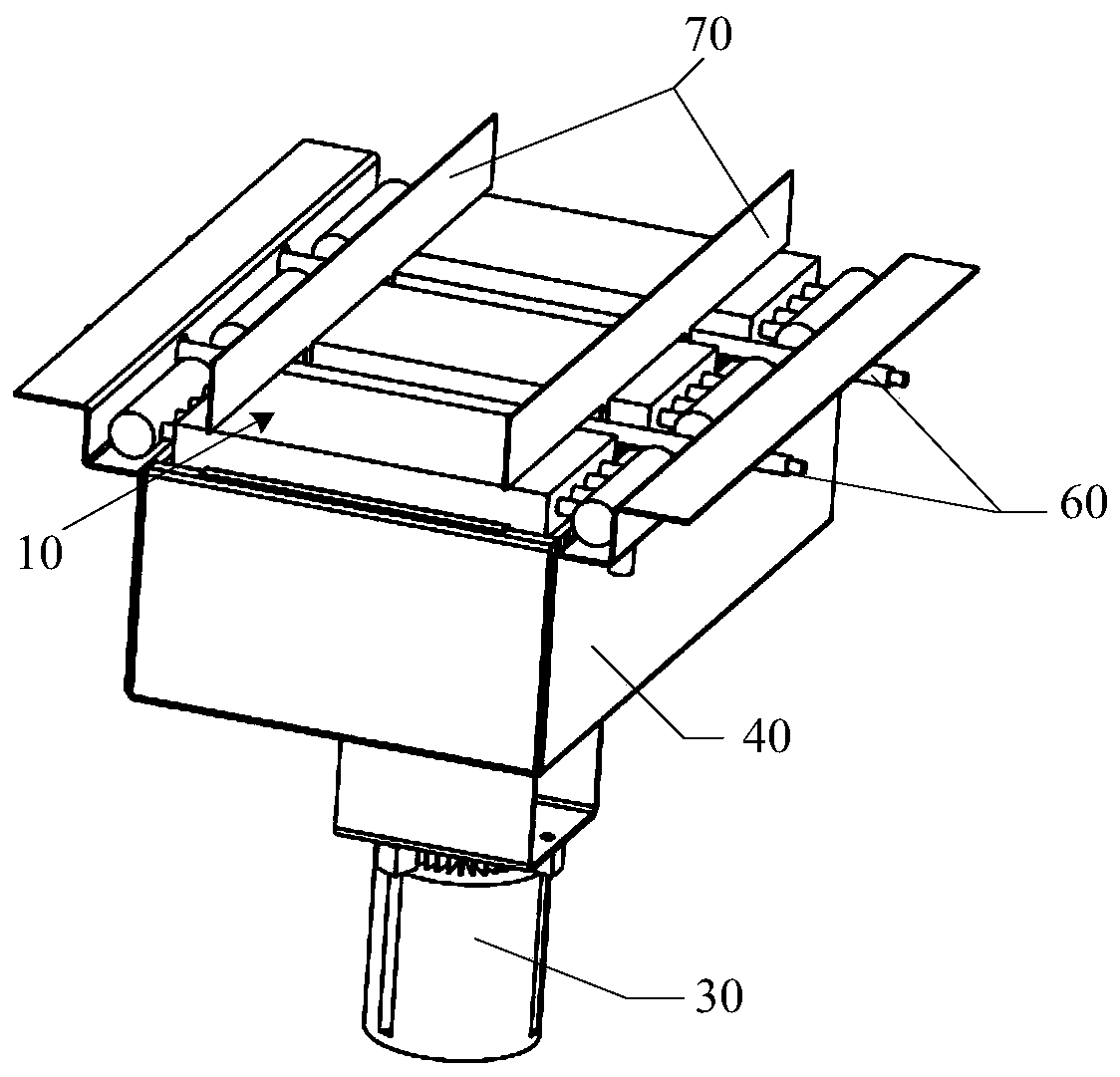
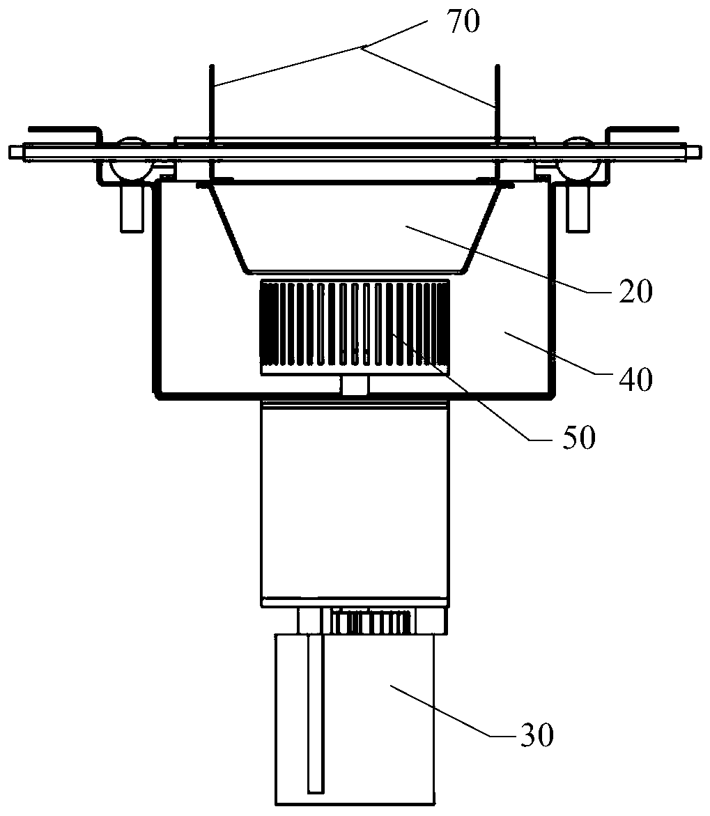
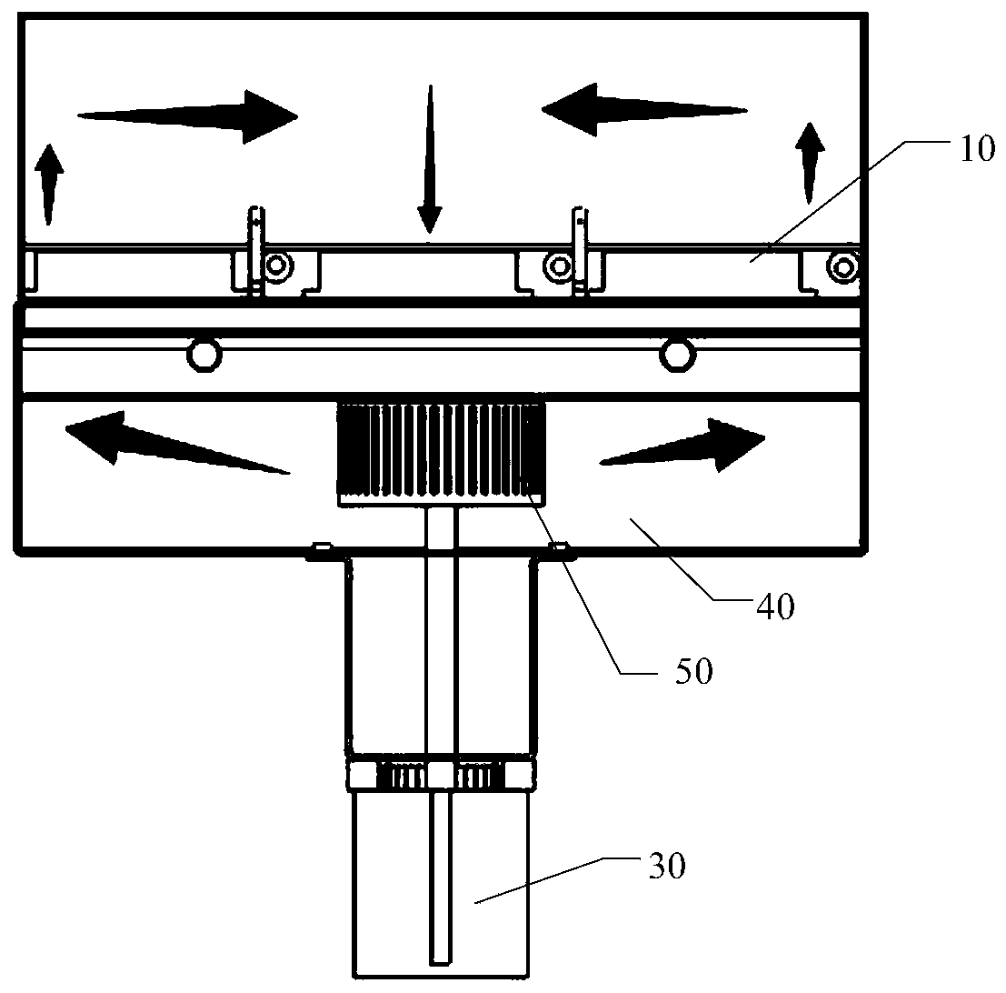
[0028] figure 1 is a schematic structural diagram of a cooling device provided in an embodiment of the present application, figure 2 It is a cross-sectional view of the cooling device provided in one embodiment of the present application. The cooling device provided by the present application includes at least one condenser 10, an inner casing 20 and an axial flow fan 30 for drafting, wherein:...


PUM


Abstract

The invention discloses a cooling device and an annealing furnace, and belongs to the technical field of battery piece production. The cooling device comprises at least one condenser, an inner shell and an axial flow fan used for sucking air, wherein the condenser is mounted at an upper end opening of the inner shell to be connected with the upper end opening of the inner shell; the axial flow fanis mounted below the inner shell and communicates with a lower end opening of the inner shell; the condenser is located below a furnace body and forms a furnace cavity together with the side walls and the upper wall of the furnace body; and after the axial flow fan runs, hot air in the furnace cavity is downwards sucked through the inner shell. The condenser is arranged at the lower end of the furnace body to form a water-cooling circulation structure of the furnace body, and the axial flow fan is arranged below the condenser, so that stable cooling of the closed cavity is realized, and the temperature is prevented from being increased or reduced sharply to damage a to-be-machined part.

Description

technical field [0001] The invention belongs to the technical field of cell production, and relates to a cooling device and an annealing furnace. Background technique [0002] In the production process of the battery sheet, the battery sheet needs to be put into the annealing furnace for annealing treatment, and the annealing process involves the technical requirements for temperature reduction in the furnace body. [0003] When controlling the temperature in the traditional furnace body, the temperature in the furnace body is usually controlled by controlling the power of the infrared lamp. However, it is relatively easy to control the infrared lamp tube to increase the temperature of the furnace body, but it is difficult to reduce the temperature of the furnace body by reducing the power of the infrared lamp tube, and it is difficult to accurately control the temperature of the furnace body. Contents of the invention [0004] In order to solve the problem in the related...

Claims


Application Information

Patent Timeline
Patent Type & Authority Applications(China)
IPC IPC(8): H01L31/18
CPCH01L31/1864Y02P70/50
Inventor 李文周凡郭健李涛
Owner 无锡奥特维旭睿科技有限公司
Why Eureka
Eureka Blog
Learn More