Eureka AIR delivers breakthrough ideas for toughest innovation challenges, trusted by R&D personnel around the world.

Self-adjusting light filtering monitor

A monitor and filter plate technology, which is applied in the direction of photographic filters, optics, instruments, etc., can solve the problems of blurred pictures taken by the monitor and affect the normal use of the monitor, so as to improve the shooting clarity and reduce the Influence and improve the effect of cleaning effect

Active Publication Date: 2019-07-19
嘉兴方沐能源科技有限公司
View PDF12 Cites 2 Cited by
  • Summary
  • Abstract
  • Description
  • Claims
  • Application Information

AI Technical Summary

Problems solved by technology

[0003] Since the shooting principle of the monitor is the principle of optical imaging, if the external light is too strong during use, it will cause the monitor to shoot the picture blurred and affect the normal use of the monitor.

Method used


Image

  • Self-adjusting light filtering monitor
  • Self-adjusting light filtering monitor
  • Self-adjusting light filtering monitor

Examples


Embodiment 1

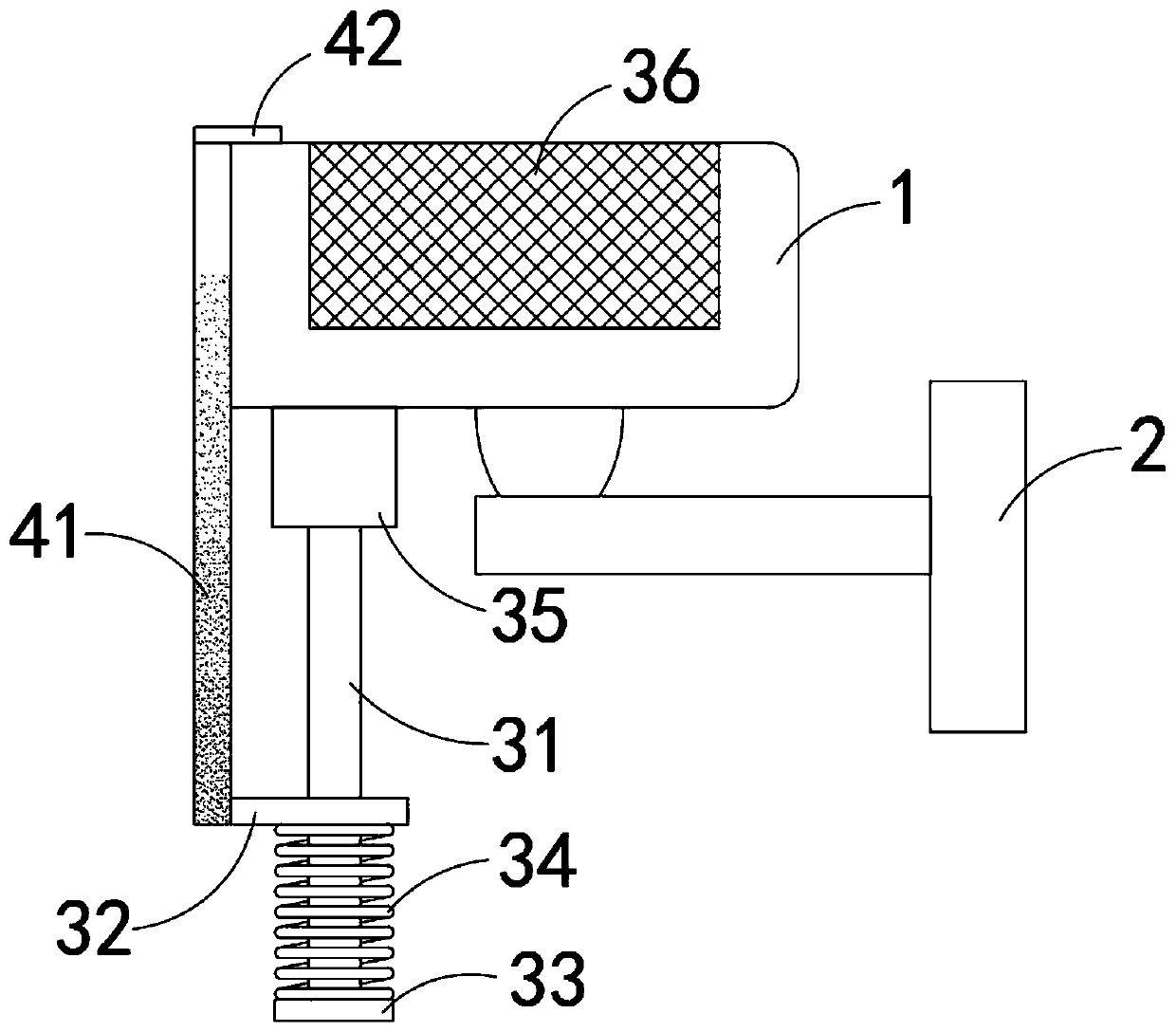
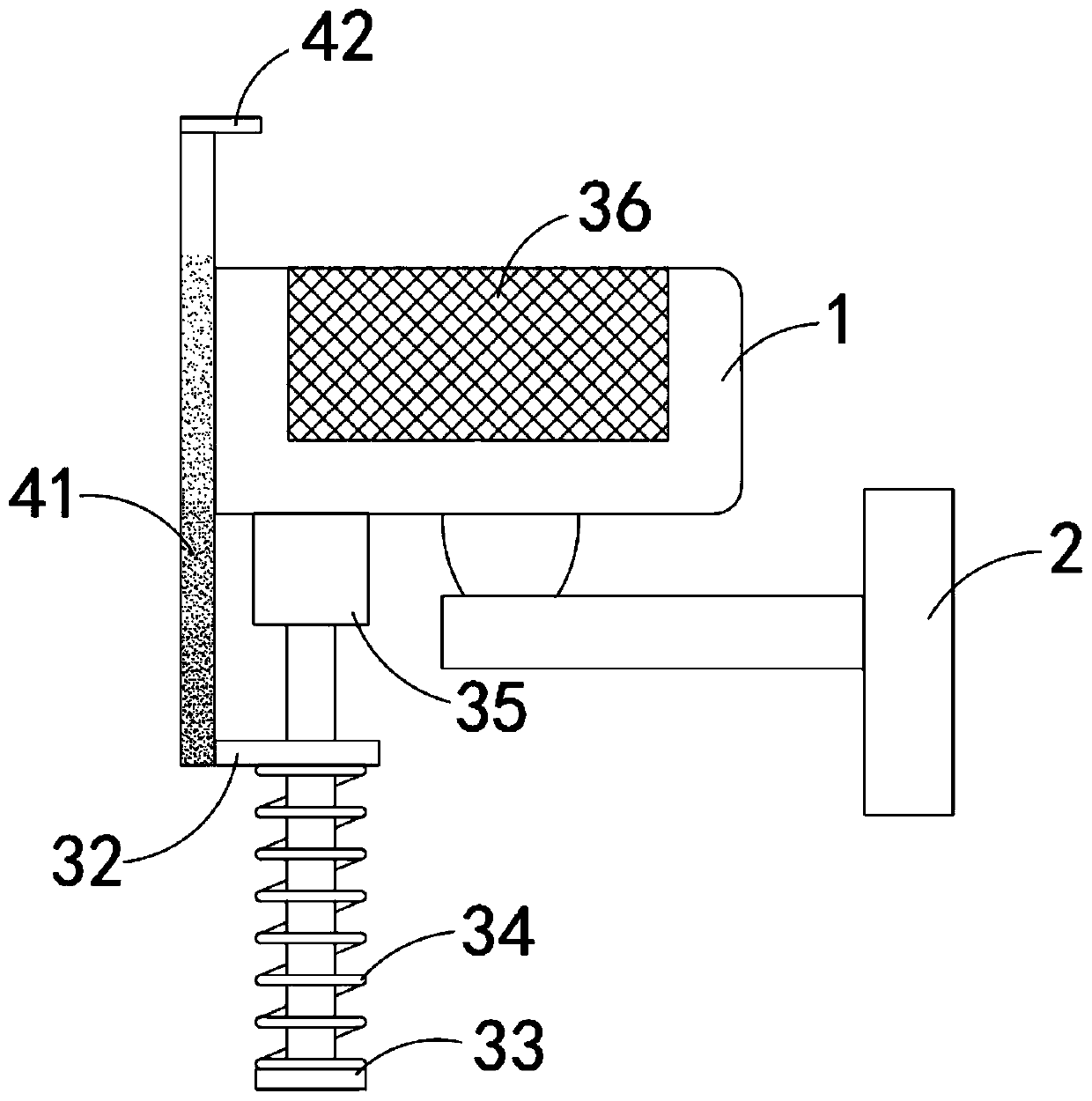
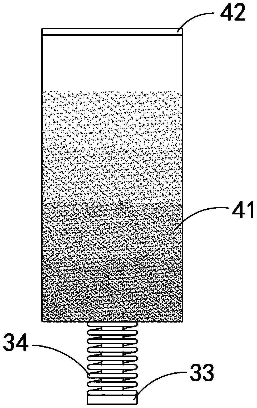
[0030] Such as Figure 1-3 As shown, a self-adjusting filter monitor includes a monitor body 1 and a bracket 2. The monitor body 1 is fixedly mounted on the bracket 2. The monitor body 1 is provided with a drive mechanism and a filter mechanism. The drive mechanism includes:

[0031] Sliding bar 31, and sliding bar 31 is vertically arranged, and the upper end of sliding bar 31 is fixedly connected on the lower side wall of monitor body 1; Ferromagnetic plate 32, ferromagnetic plate 32 is made of ferromagnetic material, and can Displacement is generated below, and the ferromagnetic plate 32 is slidably sleeved on the sliding rod 31;

[0032] Limit block 33, and limit block 33 is fixedly connected in the lower end of slide bar 31; Back-moving spring 34, back-moving spring 34 is sleeved on the slide bar 31, and the upper and lower ends of back-moving spring 34 are connected with ferromagnetic plate 32 and limit block respectively The side wall of 33 is fixedly connected; Electro...

Embodiment 2

[0038] Such as Figure 4-5 As shown, the difference between this embodiment and Embodiment 1 is that: the side of the filter plate 41 away from the monitor body 1 is provided with two cleaning strips 5 arranged side by side, the cleaning strips 5 are arranged horizontally, and the cleaning strips 5 and the filter plate The side walls of 41 are attached, and two cleaning strips 5 are respectively located on the upper and lower sides of the monitor body 1 lens, and the cleaning strips 5 are fixedly connected to the monitor body 1 .

[0039] In this embodiment, when the filter plate 41 moves up and down, since the cleaning strip 5 is fixed to the monitor body 1, a relative displacement occurs between the cleaning strip 5 and the filter plate 41, so that the side wall of the filter plate 41 can be adjusted. Clean, so that the monitor body 1 can take pictures more clearly.


PUM


Abstract

The invention belongs to the field of monitor equipment, and particularly relates to a self-adjusting light filtering monitor. The self-adjusting light filtering monitor comprises a monitor body and asupport; the monitor body is fixedly mounted on the support; a driving mechanism and a light filtering mechanism are arranged on the monitor body; and the driving mechanism comprises a sliding rod arranged vertically and of which the upper end is fixedly connected to the lower side wall of the monitor body, a ferromagnetic plate arranged on the sliding rod in a sliding and sleeving mode, a limiting block fixedly connected to the lower end of the sliding rod, a reset spring arranged on the sliding rod in a sleeving mode and of which the upper end and the lower end are fixedly connected with the side walls of the ferromagnetic plate and the limiting block respectively, and an electromagnet fixedly connected to the upper end of the sliding rod. The position of a light filtering plate can beautomatically adjusted according to the illumination intensity, and the light filtering effect of the monitor is realized, so that the monitor can stably perform shooting under strong light; and the light filtering plate can be cleaned under the action of a cleaning strip.

Description

technical field [0001] The invention belongs to the field of monitor equipment, in particular to a self-adjusting filter monitor. Background technique [0002] With the increasing popularity of closed-circuit surveillance in civil and commercial purposes, surveillance cameras are widely used in various fields to protect enterprise management and social security. [0003] Since the principle of monitor shooting is the principle of optical imaging, if the external light is too strong during use, the picture taken by the monitor will be blurred and affect the normal use of the monitor. [0004] For this reason, we propose a self-tuning filter monitor to solve the above problems. Contents of the invention [0005] The object of the present invention is to provide a self-adjusting filter monitor based on a solar power generation system to solve the problem that the monitor takes blurred pictures under strong light. [0006] In order to achieve the above object, the present in...

Claims


Application Information

Patent Timeline
Patent Type & Authority Applications(China)
IPC IPC(8): G03B11/00B08B1/02
CPCG03B11/00B08B1/20
Inventor 吴坚鹏
Owner 嘉兴方沐能源科技有限公司
Why Eureka
Eureka Blog
Learn More