Adjustable card stamping and printing mechanism

A printing mechanism and adjustable technology, applied in stamping, printing and other directions, can solve the problems of low efficiency of stamping die, and achieve the effect of high printing efficiency and simple structure

Pending Publication Date: 2018-07-31
BEAUTIFUL CARD TECH SUZHOU CO LTD
View PDF5 Cites 2 Cited by
  • Summary
  • Abstract
  • Description
  • Claims
  • Application Information

AI Technical Summary

Problems solved by technology

[0003] The technical problem to be solved by the present invention is to provide an adjustable card stamping and printing mechanism to solve the problem of low efficiency of manually adjusting the stamping die

Method used


Image

  • Adjustable card stamping and printing mechanism
  • Adjustable card stamping and printing mechanism
  • Adjustable card stamping and printing mechanism

Examples


Embodiment Construction

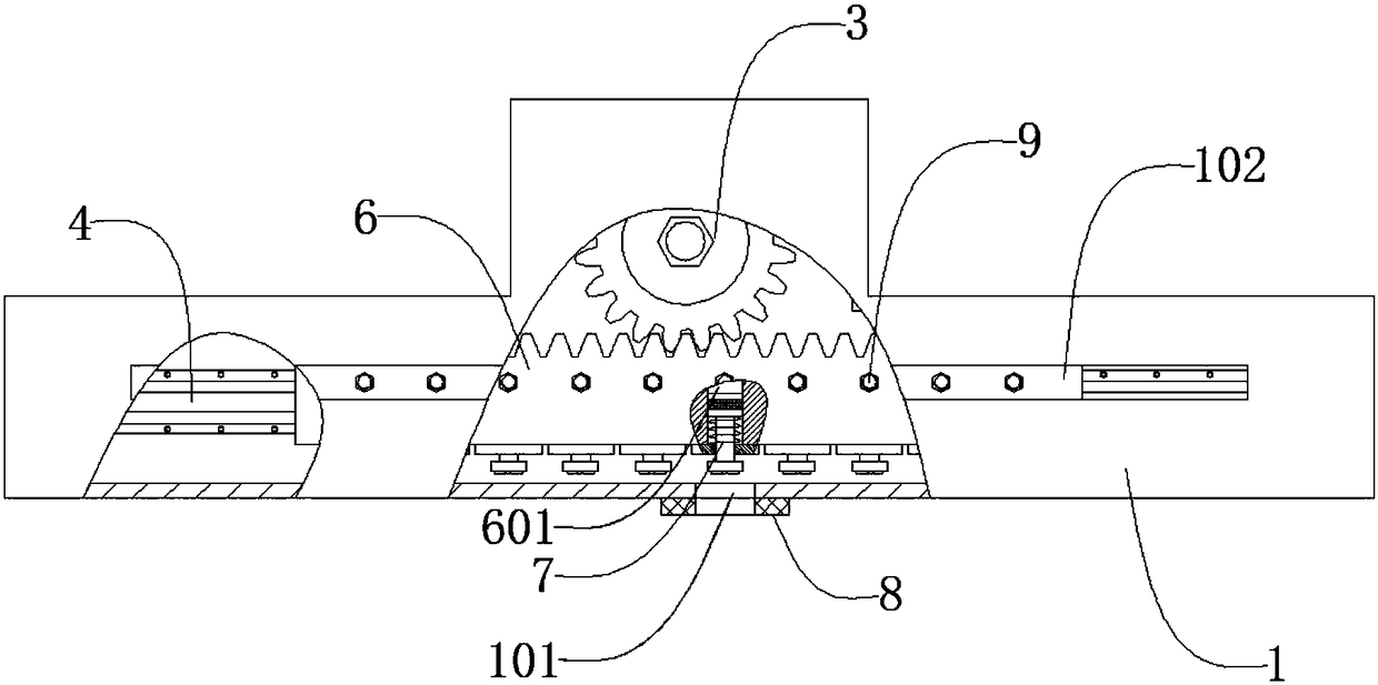
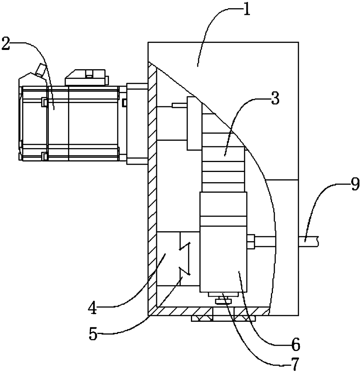
[0017] Such as figure 1 , figure 2 , image 3 As shown, an adjustable card stamping and printing mechanism includes a housing 1, a servo motor 2, a gear 3, a guide rail 4, a slider 5, a rack 6, a stamping and printing mechanism 7, a pressure plate 8, and an air pipe 9. The servo The motor 2 is located at the upper end of the outer side of the housing 1, the servo motor 2 is connected to the housing 1 by bolts, the gear 3 is located at the upper end of the inner side of the housing 1 and on the side of the servo motor 2, the gear 3 and the servo motor 2 keys are connected, the guide rail 4 is located at the lower end of the inner side of the housing 1, the guide rod 4 is connected with the housing 1 through bolts, the guide rail 4 runs through the slider 5, and the slider 5 can move along the guide rail 4 Sliding, the rack 6 is located outside the guide rail 4 and at the lower end of the gear 3, the rack 6 is connected to the guide rail 4 through bolts and meshed with the ge...


PUM


Abstract

The invention discloses an adjustable card stamping and printing mechanism which comprises a shell, a servo motor, a gear, a guide rail, a sliding block, a rack, a stamping and printing mechanism, a pressing plate and an air pipe. In the working process, ten printing dies machine the numbers of 0-9 correspondingly, a card is placed at the lower end of a pressing plate, the servo motor drives the gear to rotate and then drives the sliding block fixedly connected with the rack to move along the guide rail, the rotating angle of the servo motor is controlled so as to accurately convey any one printing die to the position over a standard site hoe formed in the shell, then, high-pressure compressed gas is pumped into a gas storage groove through the air pipe, the compressed air pushes a pistonto move downwards, then, a stamping rod fixedly connected with the piston is driven to move downwards, and therefore the printing dies are driven to carry out stamping and printing through the standard site hole and the pressing plate. The mechanism is simple in structure, capable of automatically adjusting the positions of the printing dies, applicable to stamping and printing of different numbers accordingly and high in printing efficiency.

Description

technical field [0001] The invention relates to a mechanical device, in particular to an adjustable card punching and printing mechanism. Background technique [0002] The existing electronic chip card is composed of a card body and a chip arranged on the card body, and a sensing coil connected with the chip to form a conduction is buried inside the card body, thereby forming an electronic chip card. Electronic chip cards often use a steel die to stamp numbers and other information on the card. The stamping process is: place the chip card on the positioning plate, and use the stamping steel die to stamp the chip card directly. Since the stamping steel die is printed with numbers Most of the molds need to be adjusted manually, which is not only time-consuming, but also difficult to adjust. In view of the above defects, it is necessary to design an adjustable card stamping and printing mechanism. Contents of the invention [0003] The technical problem to be solved by the ...

Claims


Application Information

Patent Timeline
Patent Type & Authority Applications(China)
IPC IPC(8): B41K3/04B41K3/62
CPCB41K3/04B41K3/62
Inventor 郑孟仁
Owner BEAUTIFUL CARD TECH SUZHOU CO LTD
Why Eureka
Try Eureka