Equipment cooling device

A technology for equipment heat dissipation and equipment, which is applied in the direction of electrical equipment structural parts, cooling/ventilation/heating transformation, electrical components, etc., can solve problems such as increasing equipment burden, and achieve the effect of reducing design burden, avoiding dust, and effectively dissipating heat

Inactive Publication Date: 2019-07-19
NEUSOFT MEDICAL SYST CO LTD
View PDF9 Cites 0 Cited by
  • Summary
  • Abstract
  • Description
  • Claims
  • Application Information

AI Technical Summary

Problems solved by technology

[0003] However, when air is introduced into the equipment box and circulated to various hot spots, issues such as dustproof and waterproof need to be considered, which increases the burden on the design of the equipment itself.

Method used


Image

  • Equipment cooling device
  • Equipment cooling device
  • Equipment cooling device

Examples


Embodiment 1

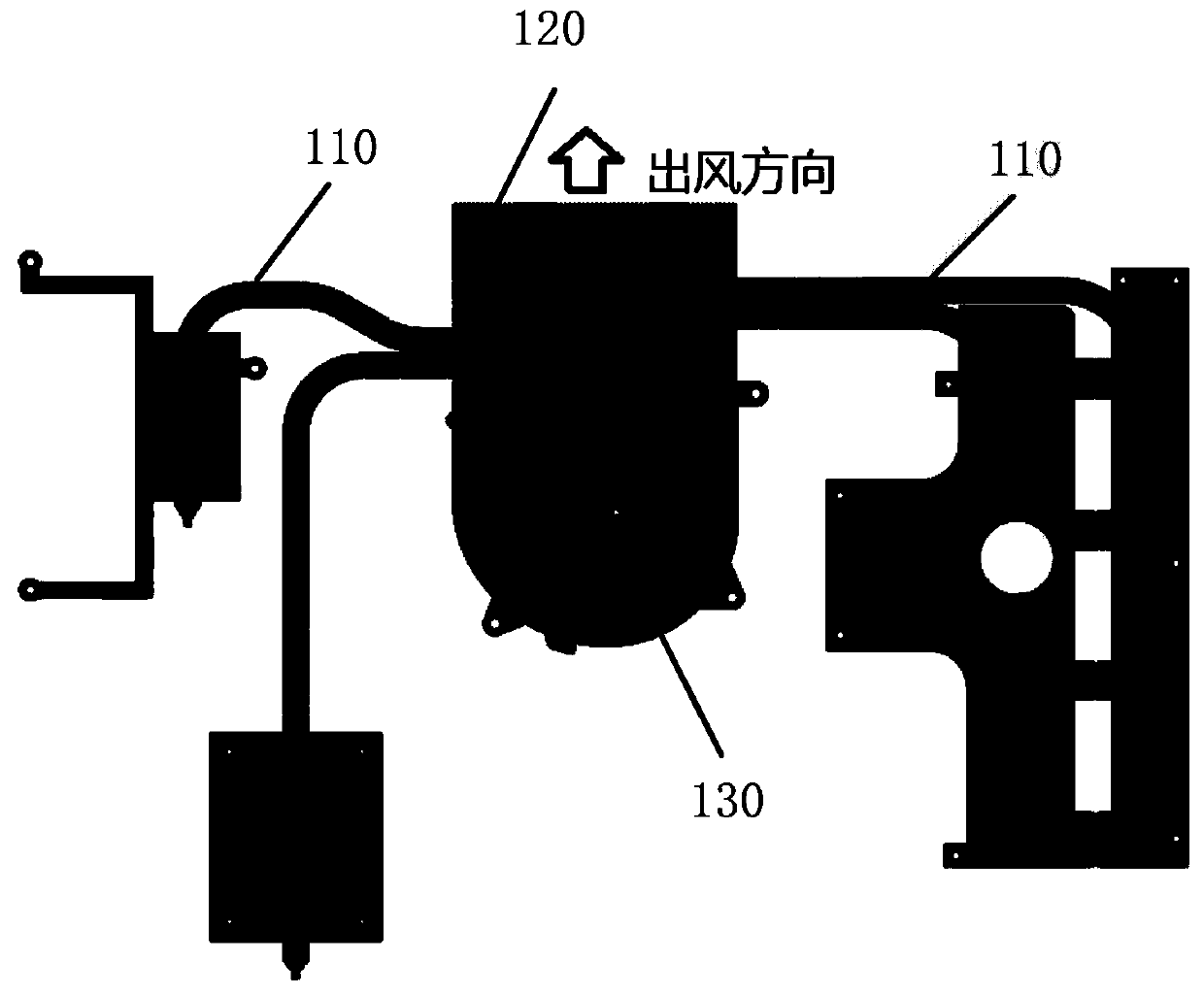
[0024] see figure 1 , which is a schematic structural diagram of a device cooling device provided in an embodiment of the present application, the device cooling device includes a heat pipe 110, a cooling fin 120 and a fan 130;

[0025] Wherein, the heat pipe 110 is installed on each heat dissipation element of the equipment, and is used for conducting the heat of each heat dissipation element to the heat dissipation fin 120;

[0026] The fan 130 is mounted on the heat sink 120 for dissipating heat from the heat sink 120 .

[0027] At present, the conduction efficiency of the heat pipe can reach more than 85%. The equipment cooling device provided by the embodiment of the present application can effectively conduct the heat of the heat source to the heat sink by using the heat pipe.

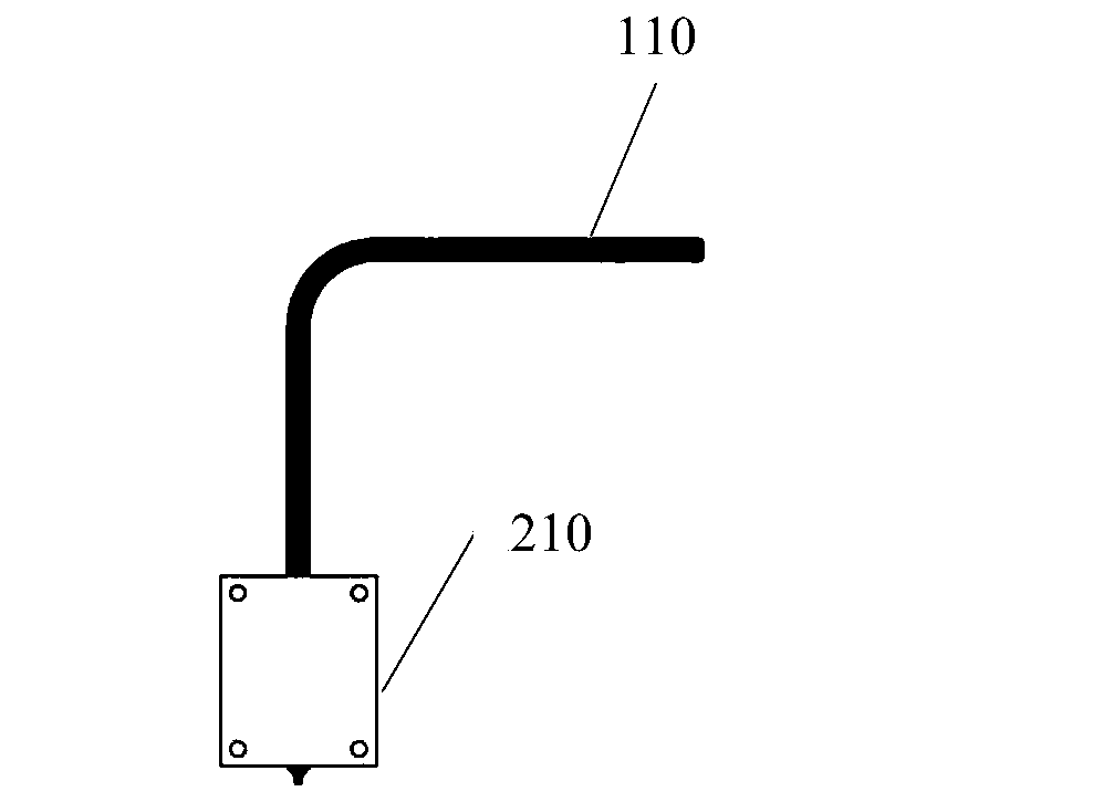
[0028] In order to achieve effective heat dissipation, at least one heat pipe is installed on each heat dissipation element of the device. If the heat pipe efficiency is insufficient, effective ...

Embodiment 2

[0035] Portable devices usually have limited internal space. If there are many heat points inside the portable device, it is obviously unfeasible to use the heat dissipation method of installing heat sinks at each heat point inside the device in the prior art. Taking portable ultrasonic equipment as an example, the current portable ultrasonic equipment on the market is to install heat sinks on each hot spot on the PCB board, and introduce air through the fan to cool each heat sink to ensure that each chip on the PCB board is in a suitable position. Reliable operation at high temperature.

[0036] In practical applications, due to the high frequency and high density of the electronic circuit in the analog signal part, the power consumption of portable ultrasound equipment is very large, and the cooling method of air duct is still widely used at present. In order to ensure the portability of the product, multiple small fans are required to be placed at the air inlet and outlet r...


PUM


Abstract

The invention discloses an equipment cooling device. The equipment cooling device comprises a hot pipe, cooling fins and a fan, wherein the hot pipe is arranged on each cooling component of equipmentand is used for uniformly conducting heat to the cooling fins, the fan is arranged on the cooling fins and is used for cooling the cooling fins so as to finally achieve the purpose of equipment cooling. Since the heat of each cooling component is conducted to the same cooling fin by a guide pipe, the cooling fin is cooled by the fan, air is not needed to be introduced to the whole box body, the problems of dust prevention, water prevention and the like are prevented, and the design burden of the equipment is reduced.

Description

technical field [0001] The present application relates to the field of heat dissipation design, in particular to a heat dissipation device for equipment. Background technique [0002] For equipment with a large number of heat-generating components and scattered locations, heat dissipation of the equipment is currently achieved by installing heat sinks at each heat-generating point. At the same time, it is also necessary to install fans to introduce air to cool the heat sinks. Ensure that each component of the equipment can operate normally at an appropriate temperature. [0003] However, when air is introduced into the equipment box and circulated to various hot spots, issues such as dustproof and waterproof need to be considered, which adds a burden to the design of the equipment itself. Contents of the invention [0004] The present application provides a heat dissipation device for equipment. The equipment equipped with the heat dissipation device can not only achieve ...

Claims


Application Information

Patent Timeline
Patent Type & Authority Applications(China)
IPC IPC(8): H05K7/20
CPCH05K7/20136H05K7/20336H05K7/20409
Inventor 于浩杨晓玲裴凯
Owner NEUSOFT MEDICAL SYST CO LTD
Why Eureka
Try Eureka