gear box clamp

A gear box and fixture technology, which is applied in the field of tooling and fixtures, can solve the problems of lack of alignment function, inconvenient use, and low work efficiency.

Active Publication Date: 2021-07-06
SUZHOU VOCATIONAL UNIV
View PDF7 Cites 0 Cited by
  • Summary
  • Abstract
  • Description
  • Claims
  • Application Information

AI Technical Summary

Problems solved by technology

[0002] The traditional gearbox fixing method adopts such as Figure 9 As shown in the clamping of the clamping plate, multiple clamping plates need to be disassembled and assembled separately, and there is no horizontal alignment function, so each clamping needs to be re-aligned and positioned, so it is inconvenient to use and the work efficiency is low

Method used


Image

  • gear box clamp
  • gear box clamp
  • gear box clamp

Examples


Embodiment Construction

[0019] The clamp of the gear box that the present invention proposes is especially suitable for such as Figure 5 In the shown gearbox, the side wall of the gearbox is symmetrically arranged with three supporting columns along the center, so that each supporting column is facing the hollow groove between the other two supporting columns.

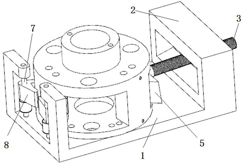
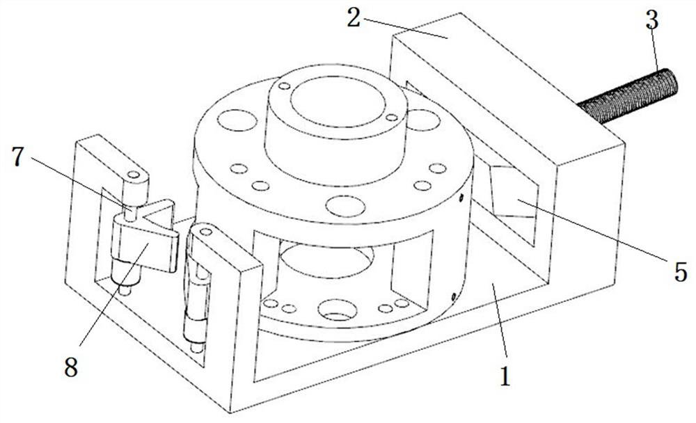
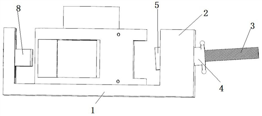
[0020] Such as Figure 1 to Figure 3 As shown, the clamp includes a base 1 and a first clamping mechanism and a second clamping mechanism oppositely arranged on the base 1 .

[0021] The first clamping mechanism includes a positioning plate 2 fixed on the base 1, a screw 3 facing the second clamping mechanism, and a screw threaded on the outside of the screw 3 such as Figure 6 The rotating threaded sleeve 4 is shown; when the rotating threaded sleeve 4 rotates, the screw rod 3 is driven to move along the straight line where the screw rod 3 is located through the thread. The rotary threaded sleeve 4 is arranged obliquely downward toward th...


PUM


Abstract

The invention discloses a gear box clamp, which includes a first clamping mechanism and a second clamping mechanism; the first clamping mechanism includes a positioning plate fixed on a base, a screw rod and a rotating threaded sleeve threaded on the outside of the screw rod; A wedge-shaped positioning block is provided on the end of the screw close to the second clamping mechanism; a positioning hole is provided on the positioning plate; the rotating threaded sleeve can be rotatably inserted into the positioning hole, and a positioning ring is fixed on the end close to the second clamping mechanism; The second clamping mechanism comprises two rotating shaft columns and a V-shaped positioning block rotatably sleeved on the rotating shaft columns. The present invention is aimed at the design of the gear box with support columns and hollow grooves respectively provided at the opposite ends of the side wall, and clamps the gear box through the wedge-shaped positioning block screwed in and the V-shaped positioning block arranged oppositely; for the same type of gear box For clamping, it only needs to be aligned at the first clamping, and there is no need for alignment and positioning when replacing parts later, and the clamping is convenient and quick, saving time and effort, and is suitable for mass production.

Description

technical field [0001] The invention relates to the field of tooling clamps, in particular to a gear box clamp. Background technique [0002] The traditional gearbox fixing method adopts such as Figure 9 The clamping of the clamping plate shown requires disassembly and assembly of multiple clamping plates, and does not have the function of aligning in the horizontal direction, so each clamping needs to be re-aligned and positioned, so it is inconvenient to use and low in work efficiency. Contents of the invention [0003] In order to solve the above problems, the present invention provides a gear box clamp. For the clamping of the same type of gear box, it only needs to be aligned when clamping for the first time, and it is not necessary to align and position when replacing parts later, and the clamping is convenient. Fast, time-saving and labor-saving, suitable for mass production. [0004] Technical solution: A clamp for a gear box, the opposite ends of the side wall o...

Claims


Application Information

Patent Timeline
Patent Type & Authority Patents(China)
IPC IPC(8): B25B11/00
CPCB25B11/00
Inventor 盖立武王明亮王旭
Owner SUZHOU VOCATIONAL UNIV
Why Eureka
Try Eureka