
Water line mold

A mold and water pipe technology, which is applied in the field of water transport molds, can solve the problems of easy crushing of water pipes and tearing of water pipes, and achieve the effect of avoiding winding molds and optimizing actions

Pending Publication Date: 2019-07-23
精英模具(珠海)有限公司
View PDF0 Cites 0 Cited by
  • Summary
  • Abstract
  • Description
  • Claims
  • Application Information

AI Technical Summary

Problems solved by technology

[0005] In order to overcome the deficiencies of the prior art and solve the problem that the water pipe is easily wound around the mold and / or the water pipe is easily crushed, the technical solution adopted by the present invention is:

Method used


Image

  • Water line mold
  • Water line mold
  • Water line mold

Examples


Embodiment Construction

[0019] The specific embodiments of the present invention will be further described in detail below in conjunction with the accompanying drawings.

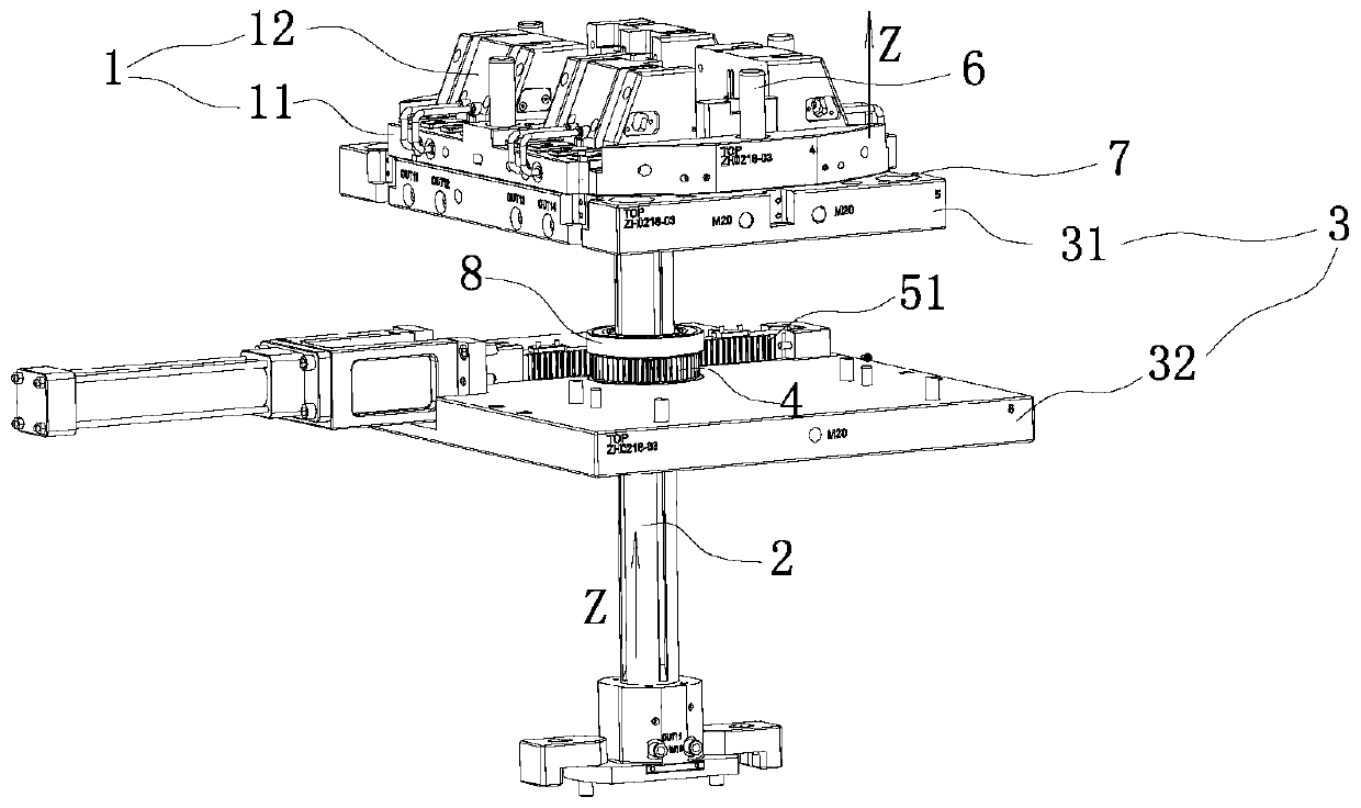
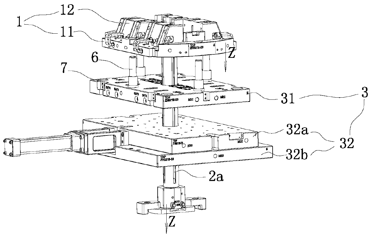
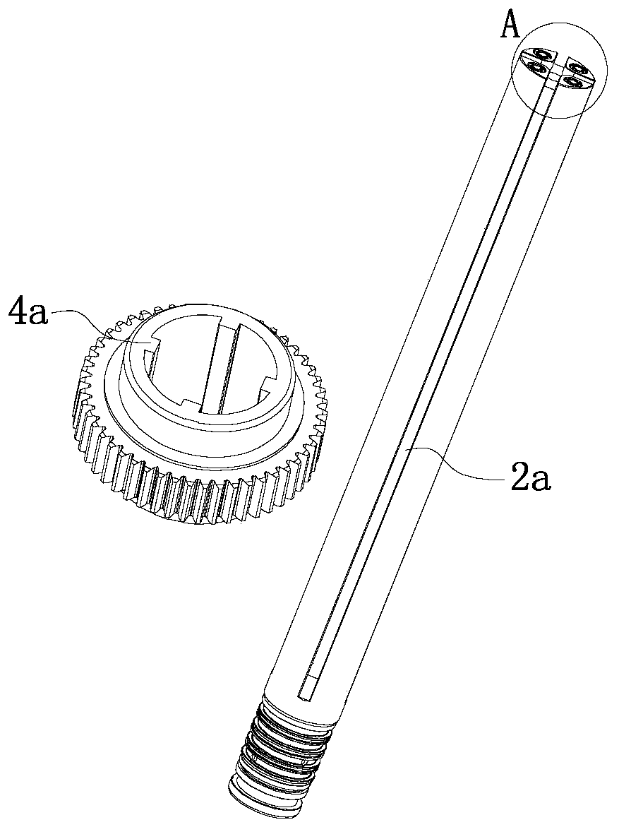
[0020] Such as Figure 1 to Figure 3 Shown, a kind of water conveying mold comprises upper mold, lower mold 1, rotating shaft 2 and fixed plate 3, and mold cavity is formed when upper mold and lower mold 1 close molds; Fixed plate 3 is provided with rotor 4 and rotating power part, The middle part of the rotating shaft 2 passes through the rotor 4, and the rotating shaft 2 is provided with a vertical chute 2a, and the inner ring of the rotor 4 is provided with a bump 4a for connecting the chute 2a; The center slides up and down relatively (relativity of motion); the rotating power part is used to drive the rotor 4 to rotate on the fixed plate 3, and the rotor 4 is used to drive the rotating shaft 2 to rotate through its projection 4a.

[0021] Such as figure 1 and figure 2 As shown, the upper mold, the lower mold 1 and the fixe...


PUM


Abstract

The invention discloses a water line mold. According to the water line mold, a cavity is formed when an upper mold and a lower mold are closed; a fixing plate is provided with a rotor and a rotating power part; a vertical chute is formed in a rotating shaft; a convex block for connecting the chute is arranged on an inner ring of the rotor; when the rotating shaft rises and falls, the convex blockslides upwards and downwards relatively in the chute; the rotating power part is used for driving the rotor to rotate on the fixing plate; the rotor is used for driving the rotating shaft to rotate through the convex block of the rotor; and the rotating shaft is used for driving the lower mold to move up and down and to rotate, and circulating cooling water to the lower mold. The action of the lower mold is optimized to prevent a water pipe from winding the mold and from being easily crushed when passing through the periphery of the mold; and the water line is improved to be connected from theinside of the mold by connecting the water line inside a central rotating shaft, so that the potential danger that an external water pipe of a double injection mold is easily broken or crushed in theprocess of rotating the lower mold (the rear mold) is eliminated. After the water line is connected inside the central rotating shaft, the water flows from the center of a jacking plate to the periphery of the jacking plate.

Description

technical field [0001] The invention relates to a mold, in particular to a water transport mold. Background technique [0002] Two-color injection molds have gradually become the mainstream production tool for two-color plastic products in the injection mold industry. The application of two-color injection molds is also becoming more and more extensive. With the generative design of two-color injection molds, the application technology of two-color injection molds has also been greatly improved. [0003] For common two-color molds, the water delivery of the lower mold will be directly connected to the peripheral water nozzle (water nozzle, water pipe joint) of the lower mold, which is designed as an external water pipe; when the lower mold rotates, the water pipe needs to rotate 180° following the lower mold template. During the rotation process, if the position of the water pipe is not fixed, the water pipe will hang on the injection molding machine or the water pipe will...

Claims


Application Information

Patent Timeline
IPC IPC(8): B29C45/16B29C45/26B29C45/73B29C33/04
CPCB29C45/16B29C45/26B29C45/73B29C33/04
Inventor 董熠武梁俊豪赵玉良丘万然刘宗友
Owner 精英模具(珠海)有限公司
Learn More