Automatic printing machine drying mode and conveying manner

A drying mode and conveying method technology, which is applied in the field of drying mode and conveying method, can solve the problem that the horizontal adjustment mechanism cannot smoothly hand over the printing platen, the vertical feeding mechanism cannot be fully adjusted, the structural reliability and stability Big problems and other problems, to achieve the effect of simple structure, convenient lifting and lower energy consumption

Pending Publication Date: 2019-07-23
邱德强
View PDF10 Cites 5 Cited by
  • Summary
  • Abstract
  • Description
  • Claims
  • Application Information

AI Technical Summary

Problems solved by technology

Although the new printing machine with the above-mentioned structure increases the number of platens per unit area and improves the output, it still has certain problems: the two sets of vertical feeding mechanisms on the three-dimensional feeding and discharging frame adopt a chain structure, and the chain drives When printing the platen, the two sets of vertical feeding mechanisms cannot be completely synchronized. After accumulating errors, the heights of the printing platens of the vertical feeding mechanisms at both ends of the horizontal adjustment mechanism are not at the same level, resulting in the inability of the horizontal adjustment mechanism to hand over the printing table smoothly. bo

Method used


Image

  • Automatic printing machine drying mode and conveying manner
  • Automatic printing machine drying mode and conveying manner
  • Automatic printing machine drying mode and conveying manner

Examples


Embodiment Construction

[0029] The following examples can enable those skilled in the art to understand the present invention more comprehensively, but the present invention is not limited to the scope of the described examples.

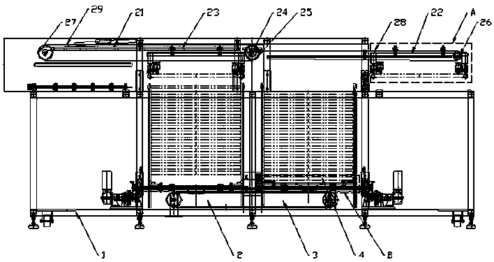
[0030] Such as figure 1 - The drying mode and conveying method of an automatic printing machine shown in the figure. The printing machine includes a printing device, a drying device and a turnover conveying device. The turnover conveying device realizes the printing of the platen between the printing device and the drying device The flow between the device and the drying device.

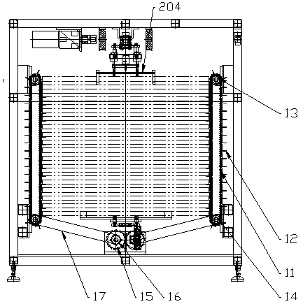
[0031] The drying device includes a box body 1, a heating device, a descending conveying mechanism, an ascending conveying mechanism, a handover device inside the pallet box, and a handover device outside the pallet box. The box body 1 has descending passages distributed side by side along the conveying direction of the pallet 3. The ascending channel 2, and the descending channel 3 communicates ...


PUM


Abstract

The invention relates to an automatic printing machine drying mode and conveying manner. A printing machine comprises a printing device, a drying device and a circulation conveying device are included. The drying device comprises a box, a heating device, a descending conveying mechanism, an ascending conveying mechanism, a table plate box interior connection device and a table plate box exterior connection device. The ascending conveying mechanism and the descending conveying mechanism are the same in structure and each comprises at least one pair of lifting chains arranged on the two sides ofthe box. The lifting chains are provided with a plurality of table plate support plates distributed in parallel. The lifting chains are driven by a drive device and drive the table plate support plates to ascend and descend up and down. The automatic printing machine drying mode and conveying manner has the advantages that through cooperation of the lifting chains and the table plate support plates, table plates ascend and descend in an ascending channel or a descending channel, for the independent ascending channel or descending channel, only a pair of lifting chains are needed, needed components are greatly reduced, the structure is simple, and lifting is convenient.

Description

technical field [0001] The invention relates to a printing machine, in particular to a drying mode and a conveying method of an automatic printing machine. Background technique [0002] As far as the current home and abroad are concerned: printing machines are mainly divided into rotary screen printing machines and flat screen printing machines according to printing plates. The printing plate of the rotary screen printing machine is a cylinder, and the rotary screen printing machine directly uses a guide belt. The printing speed is relatively fast, up to 5000m per hour, but the disadvantage is that it can only print fixed patterns, which is suitable for mass production of gray fabrics , the scope of use is narrow. The printing plate of the flat screen printing machine is a flat screen plate, and the feeding cloth of the flat screen printing machine has both a guide belt and a platen. Among them, the platen flat screen printing machine is called a circular or oval printing ...

Claims


Application Information

Patent Timeline
IPC IPC(8): B41F15/08B41F15/12B41F15/24
CPCB41F15/12B41F15/085B41F15/24B41P2215/10
Inventor 邱德强
Owner 邱德强
Why Eureka
Try Eureka