Time correction method, device, system and computer storage medium

A time correction, first-time technology, applied in the field of data processing, can solve the problems of inaccurate time measurement results, affecting the accuracy of TDC time measurement, and deviation of the true value of TDC from the design value.

Active Publication Date: 2021-02-19
湖北京邦科技有限公司
View PDF11 Cites 0 Cited by
  • Summary
  • Abstract
  • Description
  • Claims
  • Application Information

AI Technical Summary

Problems solved by technology

[0005] In the prior art, due to the influence of manufacturing process, ambient temperature, power supply voltage and other factors, the actual value of the time unit of TDC often deviates from its design value
For example, the circuit structure used to compare two input signals in the PFD cannot be completely symmetrical, which leads to an overall shift in the phase comparison result; the delay of the gate circuit will fluctuate with the manufacturing process, when the delay of the feedback signal in the PFD is short , the phase comparison result has a dead zone, that is, when the phase difference of the two input signals is smaller than the dead zone, the PFD cannot output the comparison result. When the delay of the feedback signal in the PFD is long, the phase comparison result will be in the phase lead and Repeated jumps during hysteresis lead to unstable reference voltage and affect the time unit accuracy of TDC; the structure of each delay unit in DLL and ring oscillator cannot be completely consistent, which leads to the delay signal output by each delay unit. The delay times are not equal, causing the true value of the time unit to deviate from its designed value
In TDC, the deviation of the real value of the time unit from its design value will lead to inaccurate time measurement results, which will affect the time measurement accuracy of TDC

Method used


Image

  • Time correction method, device, system and computer storage medium
  • Time correction method, device, system and computer storage medium
  • Time correction method, device, system and computer storage medium

Examples


Embodiment Construction

[0091] The technical solutions in the embodiments of the present application will be clearly and completely described below in conjunction with the accompanying drawings in the embodiments of the present application. Obviously, the described embodiments are only used to explain a part of the embodiments of the present application, not all Examples are not intended to limit the scope of the application or the claims. Based on the embodiments in this application, all other embodiments obtained by persons of ordinary skill in the art without making creative efforts shall fall within the scope of protection of this application.

[0092] It should be noted that when an element is referred to as being “disposed on” another element, it may be directly disposed on the other element or there may also be an intervening element. When an element is referred to as being "connected / coupled" to another element, it can be directly connected / coupled to the other element or intervening elements...


PUM


Abstract

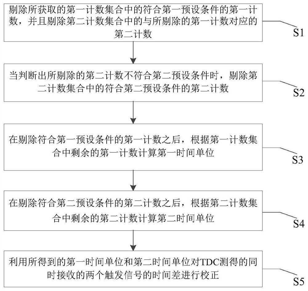
The embodiment of the present application discloses a time correction method, device, system, and computer storage medium. The method includes: removing the first counts in the obtained first count set that meet the first preset condition, and removing the first counts in the second count set The second count corresponding to the rejected first count, wherein, the first count and the second count are respectively one and the other of the coarse count and the fine count generated by TDC; when the rejected second count does not meet For the second preset condition, the second count in the second count set meeting the second preset condition is eliminated; the first time unit is calculated according to the remaining first count in the first count set; the first time unit is calculated according to the remaining first count in the second count set The second counting calculates the second time unit; the time difference of the two trigger signals is corrected by using the obtained first time unit and the second time unit. The accuracy of the time measurement result of the TDC can be improved by utilizing the technical solutions provided by the embodiments of the present application.

Description

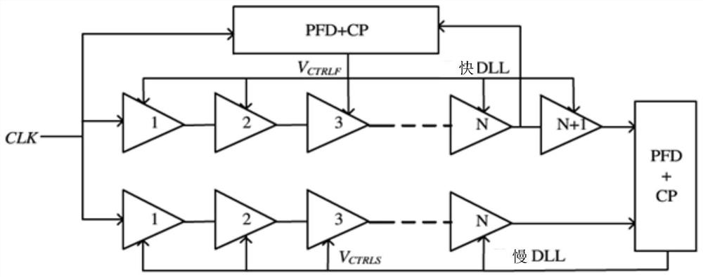
technical field [0001] The present application relates to the technical field of data processing, and in particular to a time correction method, device, system and computer storage medium. Background technique [0002] The descriptions in this section merely provide background information related to the disclosure in this application and may not constitute prior art. [0003] The time-to-digital converter (TDC) can convert the time signal to be measured into a numerical code according to the designed time unit, and then restore the time information of the time signal to be measured by multiplying the obtained numerical code by the designed time unit. The restoration accuracy is high, so it is widely used in high-precision time measurement systems. [0004] TDC generally adopts a delay-locked loop (DLL) circuit, which mainly includes two delay-locked fast DLLs and slow DLLs composed of a delay unit, a phase frequency detector (PFD), a charge pump (CP), and a ring oscillator....

Claims


Application Information

Patent Timeline
Patent Type & Authority Patents(China)
IPC IPC(8): G04F10/00H03K21/40H03L7/10
CPCG04F10/005H03K21/40H03L7/10
Inventor 张玺徐青王麟
Owner 湖北京邦科技有限公司
Why Eureka
Try Eureka