A Ring Oscillator Integrated Circuit for Multi-channel Time Measurement

A time measurement, integrated circuit technology, used in CAD circuit design, electrical digital data processing, special data processing applications, etc., can solve the accuracy and linearity of measurement results, affect the linearity of measurement results, and the unusable chip area, etc. It can reduce the total length of traces, facilitate layout and routing, and improve the accuracy of time measurement.

Active Publication Date: 2021-01-08
BEIJING MXTRONICS CORP +1
View PDF7 Cites 0 Cited by
  • Summary
  • Abstract
  • Description
  • Claims
  • Application Information

AI Technical Summary

Problems solved by technology

However, when the delay lines are connected end to end to form a ring vibration to reduce hardware overhead, because the end-to-end processing of the loop structure may destroy the original linear structure, it may affect the accuracy and linearity of the measurement results
[0008] If the ring vibration is laid out in a straight line, and the signal is fed back to the starting position of the ring vibration through the connection at the end, it will cause a large line delay for the end-to-end connection, which will affect the linearity of the measurement results, especially In the deep submicron integrated circuit process, the line delay occupies a larger proportion than the gate delay, and the influence of the line delay on the ring oscillator design must be considered
[0009] If the layout of the ring vibration is also arranged in a ring during design, the linearity of the ring vibration result can be better guaranteed, but there will be a lot of chip area in the center of the ring and outside the ring that cannot be used, resulting in waste of chip area and increasing the cost of implementation.

Method used


Image

  • A Ring Oscillator Integrated Circuit for Multi-channel Time Measurement
  • A Ring Oscillator Integrated Circuit for Multi-channel Time Measurement
  • A Ring Oscillator Integrated Circuit for Multi-channel Time Measurement

Examples


Embodiment Construction

[0036] The present invention will be described in detail below in conjunction with the accompanying drawings and specific embodiments.

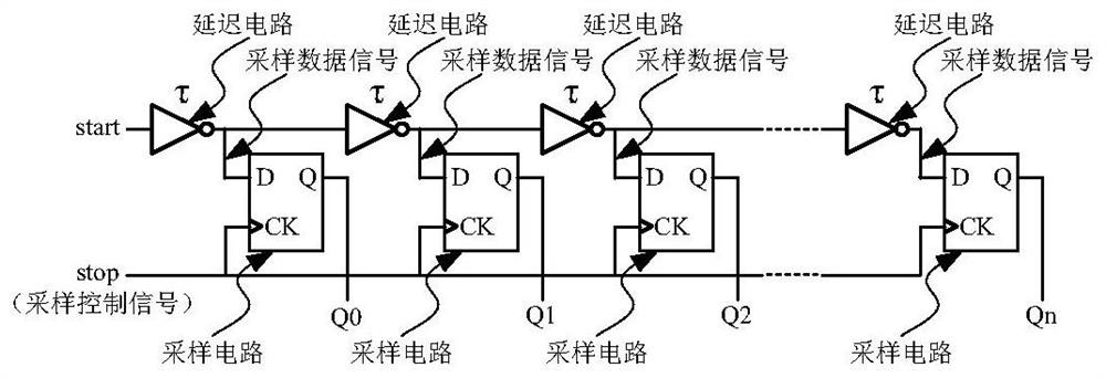
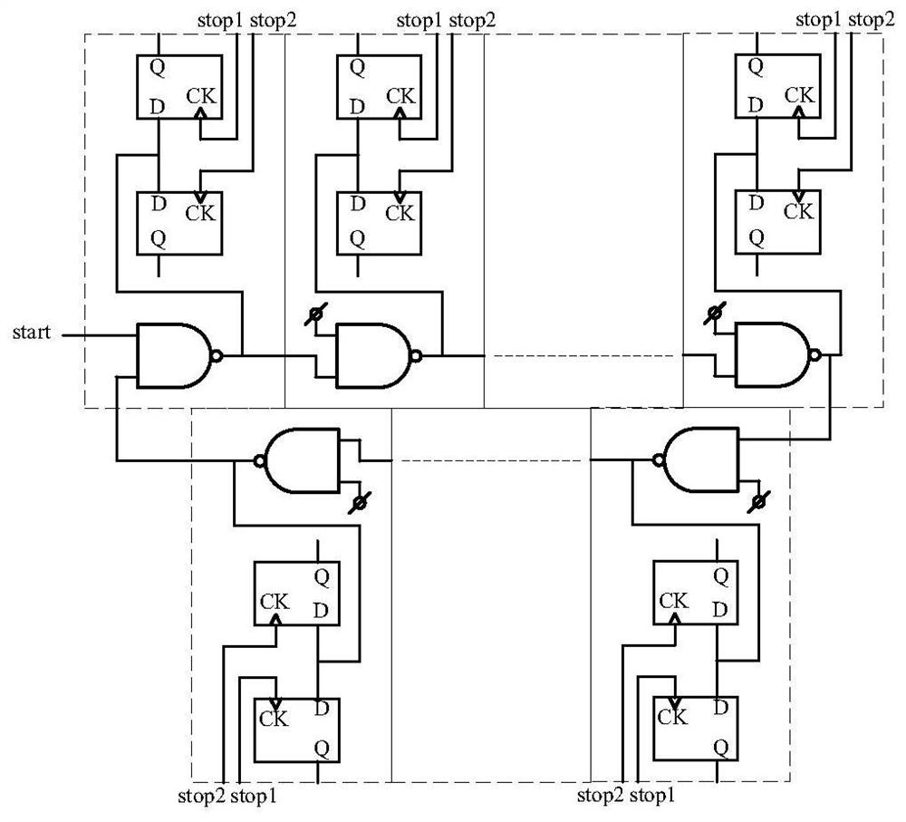
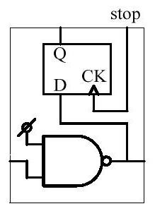
[0037] The layout design of the ring oscillator circuit needs to ensure that the delay time and sampling time of the units at all levels are uniform, consistent and accurate, so as to reduce the nonlinear factors introduced by the design and provide as accurate and reliable measurement results as possible. This puts high demands on the design of the ring oscillator itself, the delay and the sampling part. Reasonable ring vibration layout design plays an important role in improving the linearity of measurement results, reducing measurement errors and improving chip area utilization.

[0038] The invention provides a ring oscillator integrated circuit for multi-channel time measurement. The layout design of the ring oscillator adopts a rectangular layout. The ring oscillator unit is arranged sequentially in one direction, and the delay circui...


PUM


Abstract

The invention discloses a ring oscillation integration circuit used for multi-channel time measurement. Ring oscillation units are arranged in an upper line and a lower line along the lateral direction of a layout coordinate system, wherein the delay circuits of the upper line of the ring oscillation units are positioned on the bottoms of the ring oscillation units and are in sequential cascade connection along the positive direction of the horizontal axis of the layout coordinate system; the delay circuits of the lower line of the ring oscillation units are positioned on the tops of the ringoscillation units and are in sequential cascade connection along the negative direction of the horizontal axis of the layout coordinate system; the delay circuits of all ring oscillation units form anend-to-end delay chain; signal delay time between the delay circuits of two adjacent ring oscillation units is equal; an externally-input tested signal start is transmitted in the annular delay chain; and under the driving of a sampling control signal, the ring oscillation units collect the states of the output ends of the delay circuits of the ring oscillation units in parallel to realize multichannel time measurement for the same signal. By use of the ring oscillation circuit, the linearity of a measurement result can be improved, measurement errors are reduced, and the area use ratio of achip is improved.

Description

technical field [0001] The invention relates to a ring vibration integrated circuit for multi-channel time measurement, which can be used in the layout design process of integrated circuits in the field of high-resolution time measurement, and belongs to the technical field of integrated circuit design. Background technique [0002] As a basic physical quantity, time plays an extremely important role in space exploration, high-energy physics, remote sensing and telemetry, and the measurement of flow and distance. Time measurement refers to the measurement of a time period, that is, the measurement of the time interval between the start signal start and the end signal stop is to be completed. There are many ways to realize high-precision time measurement through electronic circuits, and the more common method at present is the tapped delay line method. [0003] The principle of the tapped delay line method is to make the measured start signal pass through the delay line, and...

Claims


Application Information

Patent Timeline
Patent Type & Authority Patents(China)
IPC IPC(8): G06F30/392G06F115/06
CPCG06F30/392G06F2115/06
Inventor 蒋安平胡贵才胡文瑞
Owner BEIJING MXTRONICS CORP
Why Eureka
Try Eureka