
Time accuracy calibration method, device and electronic equipment

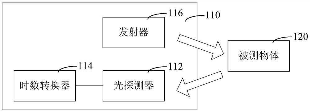
A technology of time accuracy and calibration method, applied in measurement devices, re-radiation of electromagnetic waves, radio wave measurement systems, etc., can solve problems such as minimum time accuracy deviation, inaccurate system time measurement, and inaccurate system ranging distance.

Active Publication Date: 2021-08-20
SHENZHEN ADAPS PHOTONICS TECH CO LTD
View PDF0 Cites 0 Cited by
  • Summary
  • Abstract
  • Description
  • Claims
  • Application Information

AI Technical Summary

Problems solved by technology

[0004] Therefore, in the existing time-of-flight systems related to TDC time measurement, due to the deviation of the minimum time accuracy of TDC, the system has inaccurate time measurement, which eventually leads to the problem of inaccurate distance measurement of the system

Method used


Image

  • Time accuracy calibration method, device and electronic equipment
  • Time accuracy calibration method, device and electronic equipment
  • Time accuracy calibration method, device and electronic equipment

Examples


Embodiment Construction

[0045]In order to facilitate the understanding of the present application, and to make the above-mentioned purpose, features and advantages of the present application more obvious and understandable, the specific implementation manners of the present application will be described in detail below in conjunction with the accompanying drawings. In the following description, numerous specific details are set forth to facilitate a full understanding of the application, and preferred embodiments of the application are shown in the accompanying drawings. However, the present application can be embodied in many different forms and is not limited to the embodiments described herein. On the contrary, the purpose of providing these embodiments is to make the disclosure of the application more thorough and comprehensive. The present application can be implemented in many other ways that are different from those described here, and those skilled in the art can make similar improvements wit...


PUM


Abstract

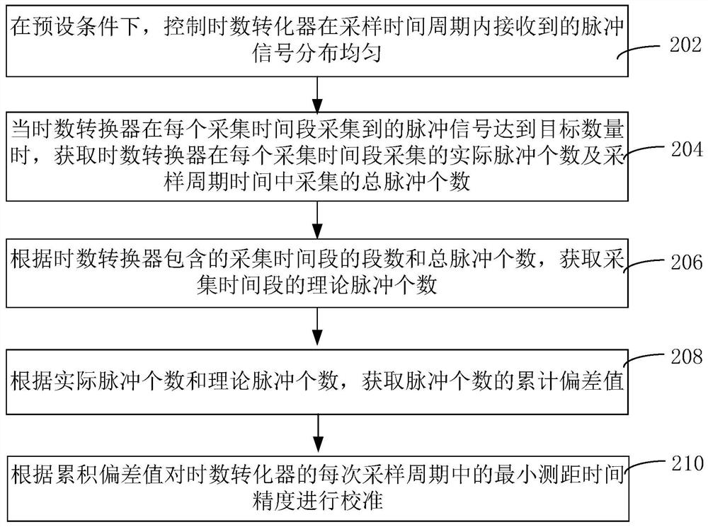
This application relates to a time accuracy calibration method, device and electronic equipment. By controlling the pulse signal received by the time-to-digital converter in each sampling period to distribute evenly, when the pulse signal collected in each collection time period reaches the target number , to obtain the actual number of pulses collected in each collection time period, the theoretical number of pulses and the total number of pulses collected in the sampling cycle time, and then obtain the cumulative deviation value of the pulse number, and finally calculate the minimum ranging time accuracy according to the cumulative deviation value Calibration is performed to improve the time measurement accuracy of the time-of-flight module. Since multiple pulse signals are evenly distributed within the sampling period of the time-to-digital converter, the number of pulse signals in each acquisition time period can reflect the time length of each minimum ranging time accuracy, thus accumulating the deviation of the number of pulses The value can realize the calibration of the minimum ranging time accuracy, and the time measurement accuracy can be effectively improved without the introduction of complex test equipment.

Description

technical field [0001] The invention relates to the field of time-of-flight ranging, in particular to a time precision calibration method, device and electronic equipment. Background technique [0002] The direct time of flight (dTof) ranging system uses a Time-to-Digital Converter (TDC) to sample and calculate the time dimension, and the time measurement accuracy of the TDC will directly affect the distance measurement of the dTof system precision. [0003] However, due to the nonlinearity of the electronics, the timing accuracy varies among multiple TDCs. The minimum ranging time precision of each TDC can be determined by the Least Significant Bit (LSB, least significant bit), and the actual minimum ranging time precision will have a slight difference from the LSB of each TDC. Therefore, within a ranging period, the difference between the actual minimum ranging accuracy and LSB will be accumulated so that the difference between the flight time collected by the TDC and th...

Claims


Application Information

Patent Timeline
Patent Type & Authority Patents(China)
IPC IPC(8): G01S7/497G01S17/14
CPCG01S7/497G01S17/14
Inventor 侯昌韬张超
Owner SHENZHEN ADAPS PHOTONICS TECH CO LTD
Learn More